


14 - 50
Chapter 14 Common Functions
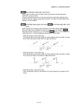
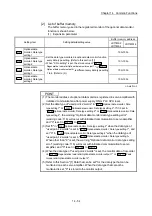
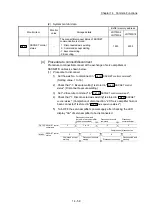
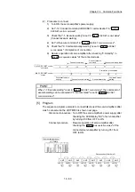
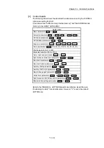
Cd.802
Latch data range change request
Request the processing of latch data range change. Set the following value
depending on the timing of updating the change value.
1 : Change in the next Operation cycle of the requested
2 : Change in the next DI input of the requested
• "0" is automatically set after receiving the latch data range change request. (It
indicates that the latch data range change is completed.)
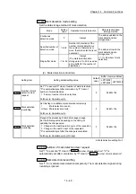
• "
Pr.805
Latch data range upper limit value
" and "
Pr.806
Latch data range lower limit
value
" at latch data range change request are used as the change value.
• Restrictions according to the type of latch data range change request are shown
below.
Types of change request
Cd.801
Mark detection invalid flag
Changing
possibility
1: Change in the next Operation
cycle of the requested
1
: Mark detection: Invalid
Other than 1: Mark detection: Valid
2: Change in the next DI input of
the requested
1
: Mark detection: Invalid
Other than 1: Mark detection: Valid
: Possible, : Not possible
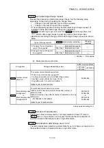
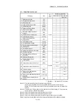
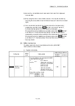
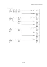
(3) Mark detection monitor data
Storage item
Storage details/storage value
Buffer memory address
LD77MS2
LD77MS4
LD77MS16
Md.800
Number of mark
detection
The number of mark detections is stored.
"0" clear is executed at power supply ON.
Continuous detection mode: 0 to 65535 (Ring counter)
Specified number of detection mode: 0 to 32
Ring buffer mode: 0 to (number of buffers - 1)
Refresh cycle: At mark detection
54960+80k
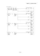
Md.801
Mark detection data
storage area 1
to
Mark detection data
storage area 32
The latch data at mark detection is stored.
Data for up to 32 times are stored in the specified number of
detection mode.
Data are stored as a ring buffer for number of detections in the ring
buffer mode.
-2147483648 to 2147483647
Refresh cycle: At mark detection
54962+80k,
54963+80k
to
55024+80k,
55025+80k
k: Mark detection setting No.-1
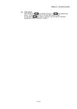
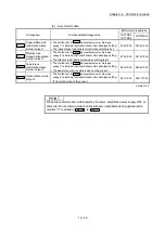
Md.800
Number of mark detection
The counter value is incremented by 1 at mark detection. Preset "0" clear in
"
Cd.800
Number of mark detection clear request
" to execute the mark detection in
specified number of detections mode or ring buffer mode.
Md.801
Mark detection data storage area 1 to 32
The latch data at mark detection is stored. Data for up to 32 times can be stored in
the specified number of detection mode or ring buffer mode.
Summary of Contents for MELSEC-L Series
Page 2: ......
Page 30: ...MEMO ...
Page 70: ...2 10 Chapter 2 System Configuration MEMO ...
Page 83: ...3 13 Chapter 3 Specifications and Functions MEMO ...
Page 103: ...3 33 Chapter 3 Specifications and Functions MEMO ...
Page 107: ...3 37 Chapter 3 Specifications and Functions MEMO ...
Page 111: ...3 41 Chapter 3 Specifications and Functions MEMO ...
Page 115: ...3 45 Chapter 3 Specifications and Functions MEMO ...
Page 140: ...4 22 Chapter 4 Installation Wiring and Maintenance of the Product MEMO ...
Page 253: ...5 113 Chapter 5 Data Used for Positioning Control MEMO ...
Page 342: ...5 202 Chapter 5 Data Used for Positioning Control MEMO ...
Page 438: ...7 20 Chapter 7 Memory Configuration and Data Process MEMO ...
Page 440: ...MEMO ...
Page 485: ...9 25 Chapter 9 Major Positioning Control MEMO ...
Page 594: ...9 134 Chapter 9 Major Positioning Control MEMO ...
Page 624: ...10 30 Chapter 10 High Level Positioning Control MEMO ...
Page 656: ...11 32 Chapter 11 Manual Control MEMO ...
Page 690: ...12 34 Chapter 12 Expansion Control MEMO ...
Page 798: ...13 108 Chapter 13 Control Sub Functions MEMO ...
Page 866: ...14 68 Chapter 14 Common Functions MEMO ...
Page 884: ...15 18 Chapter 15 Dedicated Instructions MEMO ...
Page 899: ...16 15 Chapter 16 Troubleshooting MEMO ...
Page 1036: ...Appendix 88 Appendices MEMO ...
Page 1039: ......


