


9 - 109
Chapter 9 Major Positioning Control
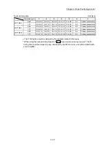
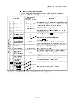
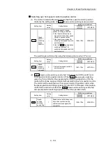
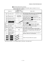
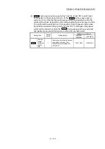
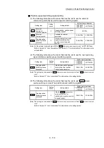
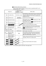
Speed-position switching signal setting
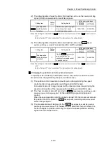
(1) The following table shows the items that must be set to use the external
command signals [DI] as speed-position switching signals.
Setting item
Setting
value
Setting details
Buffer memory address
LD77MS2
LD77MS4
LD77MS16
Pr.42
External
command
function selection
2
Speed-position, position-speed
switching request.
62+150n
Cd.8
External
command valid
1
Validates an external
command.
1505+100n 4305+100n
Cd.45
Speed-position
switching device
selection
0
Use the external command
signal for switching from speed
control to position control.
1566+100n 4366+100n
(Note): Set the external command signal [DI] in "
Pr.95
External command signal selection
" at LD77MS16 use.
Refer to Section 5.2 "List of parameters" and Section 5.7 "List of control data" for information on the
setting details.
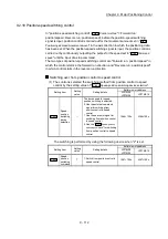
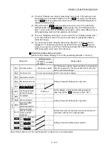
(2) The following table shows the items that must be set to use the near-point dog
signal (DOG) as speed-position switching signals.
Setting item
Setting
value
Setting details
Buffer memory address
LD77MS2
LD77MS4
LD77MS16
Cd.45
Speed-position
switching device
selection
1
Use the near-point dog signal
for switching from speed
control to position control.
1566+100n 4366+100n
(Note): The setting is not required for "
Pr.42
External command function selection
" and "
Cd.8
External command
valid
".
Refer to Section 5.7 "List of control data" for information on the setting details.
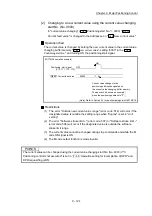
(3) The following table shows the items that must be set to use "
Cd.46
Speed-
position switching command
" as speed-position switching signals.
Setting item
Setting
value
Setting details
Buffer memory address
LD77MS2
LD77MS4
LD77MS16
Cd.45
Speed-position
switching device
selection
2
Use the "
Cd.46
Speed-position
switching command
" for
switching from speed control
to position control.
1566+100n 4366+100n
(Note): The setting is not required for "
Pr.42
External command function selection
" and "
Cd.8
External command
valid
".
Refer to Section 5.7 "List of control data" for information on the setting details.
Summary of Contents for MELSEC-L Series
Page 2: ......
Page 30: ...MEMO ...
Page 70: ...2 10 Chapter 2 System Configuration MEMO ...
Page 83: ...3 13 Chapter 3 Specifications and Functions MEMO ...
Page 103: ...3 33 Chapter 3 Specifications and Functions MEMO ...
Page 107: ...3 37 Chapter 3 Specifications and Functions MEMO ...
Page 111: ...3 41 Chapter 3 Specifications and Functions MEMO ...
Page 115: ...3 45 Chapter 3 Specifications and Functions MEMO ...
Page 140: ...4 22 Chapter 4 Installation Wiring and Maintenance of the Product MEMO ...
Page 253: ...5 113 Chapter 5 Data Used for Positioning Control MEMO ...
Page 342: ...5 202 Chapter 5 Data Used for Positioning Control MEMO ...
Page 438: ...7 20 Chapter 7 Memory Configuration and Data Process MEMO ...
Page 440: ...MEMO ...
Page 485: ...9 25 Chapter 9 Major Positioning Control MEMO ...
Page 594: ...9 134 Chapter 9 Major Positioning Control MEMO ...
Page 624: ...10 30 Chapter 10 High Level Positioning Control MEMO ...
Page 656: ...11 32 Chapter 11 Manual Control MEMO ...
Page 690: ...12 34 Chapter 12 Expansion Control MEMO ...
Page 798: ...13 108 Chapter 13 Control Sub Functions MEMO ...
Page 866: ...14 68 Chapter 14 Common Functions MEMO ...
Page 884: ...15 18 Chapter 15 Dedicated Instructions MEMO ...
Page 899: ...16 15 Chapter 16 Troubleshooting MEMO ...
Page 1036: ...Appendix 88 Appendices MEMO ...
Page 1039: ......


