

11 - 29
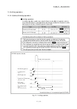
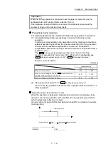
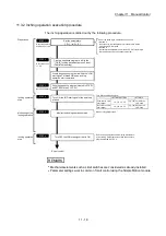
Chapter 11 Manual Control
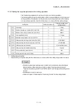
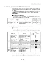
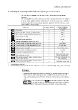
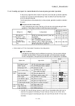
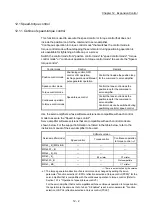
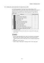
11.4.3 Setting the required parameters for manual pulse generator operation
The "Positioning parameters" must be set to carry out manual pulse generator
operation.
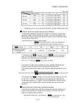
The following table shows the setting items of the required parameters for carrying out
manual pulse generator operation. Parameters not shown below are not required to be
set for carrying out only manual pulse generator operation. (Set the initial value or a
value within the setting range.)
Setting item
Setting requirement
Factory-set initial value
(setting details)
Positioning para
m
eters
Pr.1
Unit setting
3 (PLS)
Pr.2
Number of pulses per rotation (AP) (Unit: PLS)
20000
Pr.3
Movement amount per rotation (AL) (Unit: PLS)
20000
Pr.4
Unit magnification (AM)
1 (1 times)
Pr.8
Speed limit value (Unit: PLS/s)
200000
Pr.11
Backlash compensation amount (Unit: PLS)
0
Pr.12
Software stroke limit upper limit value (Unit: PLS)
2147483647
Pr.13
Software stroke limit lower limit value (Unit: PLS)
–2147483648
Pr.14
Software stroke limit selection
0 (current feed value)
Pr.15
Software stroke limit valid/invalid setting
0 (valid)
Pr.17
Torque limit setting value (Unit: %)
300
Pr.22
Input signal logic selection
0 (Manual pulse generator
input is negative logic.)
Pr.24
Manual pulse generator/Incremental synchronous
encoder input selection
0 (4 times multiplication of A
phase/B phase)
Pr.89
Manual pulse generator/Incremental synchronous
encoder input type selection
0 (Differential output type)
: Setting always required.
: Set according to requirements (Set the initial value or a value within the setting range when not used.)
REMARK
Positioning parameter settings work in common for all controls using the Simple
Motion module. When carrying out other controls ("major positioning control",
"high-level positioning control", "OPR control"), set the respective setting items as
well.
Parameters are set for each axis. But
Pr.22
Manual pulse generator input (b8),
Pr.24
,
Pr.89
is set only for axis 1. (The setting for other than axis 1 is ignored.)
Refer to Chapter 5 "Data Used for Positioning Control" for the setting details.
Summary of Contents for MELSEC-L Series
Page 2: ......
Page 30: ...MEMO ...
Page 70: ...2 10 Chapter 2 System Configuration MEMO ...
Page 83: ...3 13 Chapter 3 Specifications and Functions MEMO ...
Page 103: ...3 33 Chapter 3 Specifications and Functions MEMO ...
Page 107: ...3 37 Chapter 3 Specifications and Functions MEMO ...
Page 111: ...3 41 Chapter 3 Specifications and Functions MEMO ...
Page 115: ...3 45 Chapter 3 Specifications and Functions MEMO ...
Page 140: ...4 22 Chapter 4 Installation Wiring and Maintenance of the Product MEMO ...
Page 253: ...5 113 Chapter 5 Data Used for Positioning Control MEMO ...
Page 342: ...5 202 Chapter 5 Data Used for Positioning Control MEMO ...
Page 438: ...7 20 Chapter 7 Memory Configuration and Data Process MEMO ...
Page 440: ...MEMO ...
Page 485: ...9 25 Chapter 9 Major Positioning Control MEMO ...
Page 594: ...9 134 Chapter 9 Major Positioning Control MEMO ...
Page 624: ...10 30 Chapter 10 High Level Positioning Control MEMO ...
Page 656: ...11 32 Chapter 11 Manual Control MEMO ...
Page 690: ...12 34 Chapter 12 Expansion Control MEMO ...
Page 798: ...13 108 Chapter 13 Control Sub Functions MEMO ...
Page 866: ...14 68 Chapter 14 Common Functions MEMO ...
Page 884: ...15 18 Chapter 15 Dedicated Instructions MEMO ...
Page 899: ...16 15 Chapter 16 Troubleshooting MEMO ...
Page 1036: ...Appendix 88 Appendices MEMO ...
Page 1039: ......


