


Appendix - 28
Appendices
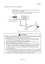
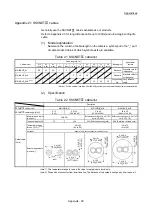
Appendix 2 Connection with servo amplifiers
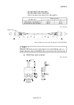
SSCNET cables are used to connect between Simple Motion module and servo
amplifier or between servo amplifiers.
Install the battery to servo amplifier to execute absolute position detection control.
Refer to each servo amplifier instruction manual for details.
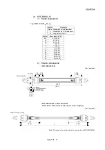
1)
Servo amplifier
CN1A
CN1B
(Note): It cannot communicate with that the connection of CN1A and CN1B is mistaken.
Cap
CN1A
CN1B
1)
Servo amplifier
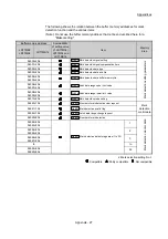
SSCNET Cable length
When MR-J3BUS_M is used
1) 3m (9.84ft.)
When MR-J3BUS_M-A is used
1) 20m (65.62ft.)
When MR-J3BUS_M-B is used
1) 50m (164.04ft.)
LD77MS
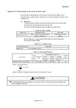
CAUTION
Be sure to connect SSCNET cable with the above connector. If the connection is mistaken, between
the Simple Motion module and servo amplifier cannot be communicated.
SSCNET connector to connect the SSCNET cable is put a cap to protect light device inside
connector from dust. For this reason, do not remove a cap until just before connecting SSCNET
cable. Then, when removing SSCNET cable, make sure to put a cap.
Keep the cap and the tube for protecting light cord end of SSCNET cable in a plastic bag with a
zipper of SSCNET cable to prevent them from becoming dirty.
Do not remove the SSCNET cable while turning on the power supply of Simple Motion module and
servo amplifier. Do not see directly the light generated from SSCNET connector of Simple Motion
module or servo amplifier and the end of SSCNET cable. When the light gets into eye, may feel
something is wrong for eye. (The light source of SSCNET cable complies with class1 defined in
JISC6802 or IEC60825-1.)
When exchanging the Simple Motion module or servo amplifier, make sure to put a cap on SSCNET
connector. When asking repair of Simple Motion module or servo amplifier for some troubles, make also
sure to put a cap on SSCNET connector. When the connector is not put a cap, the light device may
be damaged at the transit. In this case, exchange and repair of light device is required.
Summary of Contents for MELSEC-L Series
Page 2: ......
Page 30: ...MEMO ...
Page 70: ...2 10 Chapter 2 System Configuration MEMO ...
Page 83: ...3 13 Chapter 3 Specifications and Functions MEMO ...
Page 103: ...3 33 Chapter 3 Specifications and Functions MEMO ...
Page 107: ...3 37 Chapter 3 Specifications and Functions MEMO ...
Page 111: ...3 41 Chapter 3 Specifications and Functions MEMO ...
Page 115: ...3 45 Chapter 3 Specifications and Functions MEMO ...
Page 140: ...4 22 Chapter 4 Installation Wiring and Maintenance of the Product MEMO ...
Page 253: ...5 113 Chapter 5 Data Used for Positioning Control MEMO ...
Page 342: ...5 202 Chapter 5 Data Used for Positioning Control MEMO ...
Page 438: ...7 20 Chapter 7 Memory Configuration and Data Process MEMO ...
Page 440: ...MEMO ...
Page 485: ...9 25 Chapter 9 Major Positioning Control MEMO ...
Page 594: ...9 134 Chapter 9 Major Positioning Control MEMO ...
Page 624: ...10 30 Chapter 10 High Level Positioning Control MEMO ...
Page 656: ...11 32 Chapter 11 Manual Control MEMO ...
Page 690: ...12 34 Chapter 12 Expansion Control MEMO ...
Page 798: ...13 108 Chapter 13 Control Sub Functions MEMO ...
Page 866: ...14 68 Chapter 14 Common Functions MEMO ...
Page 884: ...15 18 Chapter 15 Dedicated Instructions MEMO ...
Page 899: ...16 15 Chapter 16 Troubleshooting MEMO ...
Page 1036: ...Appendix 88 Appendices MEMO ...
Page 1039: ......


