


15- 4
Chapter 15 Dedicated Instructions
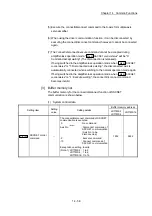
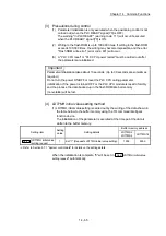
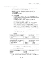
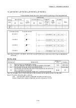
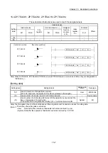
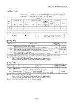
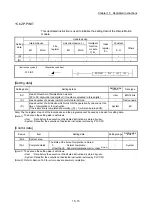
[Control data]
Device
Item
Setting data
Setting range
Setting side
(Note-1)
(S)+0 System
area
–
–
–
(S)+1 Complete
status
The state at the time of completion is stored.
• 0
: Normal completion
• Other than 0: Abnormal completion (error code)
(Note-2)
– System
(S)+2
Start No.
The following data Nos. to be started by the ZP.PSTRT_
instruction are designated.
• Positioning data No.
: 1 to 600
• Block start
: 7000 to 7004
• Machine OPR
: 9001
• Fast OPR
: 9002
• Current value changing
: 9003
• Multiple axes simultaneous start : 9004
1 to 600
7000 to 7004
9001 to 9004
User
(Note-1): The data on the setting side is as follows.
• User : Data before the execution of dedicated instructions is stored by user.
• System: Data after the execution of dedicated instruction is stored by PLC CPU.
(Note-2): Refer to Section 16.5 for error codes at abnormal completion.
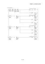
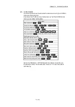
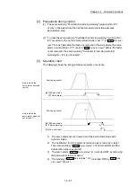
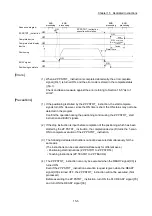
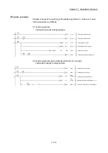
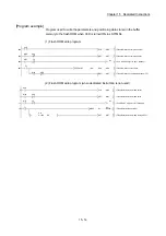
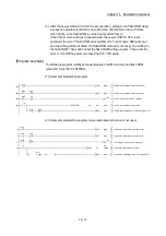
[Functions]
(1) The positioning start of the axes to be processed (See below) is carried out.
• ZP.PSTRT1: Axis 1
• ZP.PSTRT2: Axis 2
• ZP.PSTRT3: Axis 3
• ZP.PSTRT4: Axis 4
(2) The block start, OPR start, current value changing, and multiple axes
simultaneous start can be carried out by the setting of "start number" 7000 to
7004/9001 to 9004 in ((S)+2).
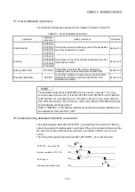
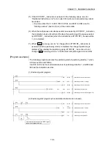
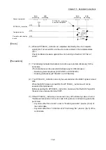
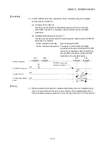
(3) The ZP.PSTRT_ instruction completion can be confirmed using the complete
devices ((D)+0) and ((D)+1).
(a) Complete device ((D)+0)
This device is turned ON by the END processing of the scan for which
ZP.PSTRT_ instruction is completed, and turned OFF by the next END
processing.
(b) Complete state display device ((D)+1)
This device is turned ON and OFF according to the state in which ZP.PSTRT_
instruction is completed.
• When completed normally : Kept unchanged at OFF.
• When completed abnormally: This device is turned ON by the END
processing of the scan for which ZP.PSTRT_
instruction is completed, and turned OFF by
the next END processing. (Same ON/OFF
operation as the complete device.)
Summary of Contents for MELSEC-L Series
Page 2: ......
Page 30: ...MEMO ...
Page 70: ...2 10 Chapter 2 System Configuration MEMO ...
Page 83: ...3 13 Chapter 3 Specifications and Functions MEMO ...
Page 103: ...3 33 Chapter 3 Specifications and Functions MEMO ...
Page 107: ...3 37 Chapter 3 Specifications and Functions MEMO ...
Page 111: ...3 41 Chapter 3 Specifications and Functions MEMO ...
Page 115: ...3 45 Chapter 3 Specifications and Functions MEMO ...
Page 140: ...4 22 Chapter 4 Installation Wiring and Maintenance of the Product MEMO ...
Page 253: ...5 113 Chapter 5 Data Used for Positioning Control MEMO ...
Page 342: ...5 202 Chapter 5 Data Used for Positioning Control MEMO ...
Page 438: ...7 20 Chapter 7 Memory Configuration and Data Process MEMO ...
Page 440: ...MEMO ...
Page 485: ...9 25 Chapter 9 Major Positioning Control MEMO ...
Page 594: ...9 134 Chapter 9 Major Positioning Control MEMO ...
Page 624: ...10 30 Chapter 10 High Level Positioning Control MEMO ...
Page 656: ...11 32 Chapter 11 Manual Control MEMO ...
Page 690: ...12 34 Chapter 12 Expansion Control MEMO ...
Page 798: ...13 108 Chapter 13 Control Sub Functions MEMO ...
Page 866: ...14 68 Chapter 14 Common Functions MEMO ...
Page 884: ...15 18 Chapter 15 Dedicated Instructions MEMO ...
Page 899: ...16 15 Chapter 16 Troubleshooting MEMO ...
Page 1036: ...Appendix 88 Appendices MEMO ...
Page 1039: ......


