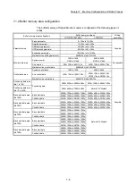


7 - 11
Chapter 7 Memory Configuration and Data Process
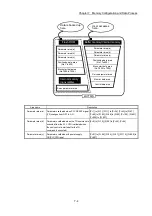
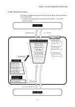
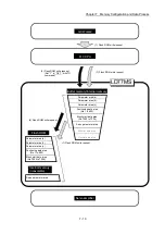
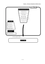
(6) Writing the flash ROM by a PLC CPU request (
)
The following transmission process is carried out by setting "1" in "
Cd.1
Flash
ROM write request
".
1) The "parameters", "positioning data (No. 1 to 600)", "block start data (No.
7000 to 7004)" and "servo parameter" in the buffer memory/internal memory
area are transmitted to the flash ROM/internal memory (nonvolatile).
The writing to the flash ROM may also be carried out using a dedicated
instruction "ZP.PFWRT". (Refer to Chapter 15 "Dedicated Instructions" for
details.)
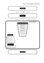
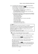
(7) Writing the flash ROM by a GX Works2 request (
)
The following transmission processes are carried out with the [flash ROM write
request] from the GX Works2.
1) The "parameters", "positioning data (No. 1 to 600)", "block start data (No.
7000 to 7004)" and "servo parameter" in the buffer memory/internal memory
area are transmitted to the flash ROM/internal memory (nonvolatile).
Note) This transmission process is the same as (6) above.
Important
(1) Do not turn the power OFF or reset the PLC CPU while writing to the flash
ROM. If the power is turned OFF or the PLC CPU is reset to forcibly end the
process, the data backed up in the flash ROM/internal memory (nonvolatile) will
be lost.
(2) Do not write the data to the buffer memory/internal memory before writing to the
flash ROM is completed.
(3) The number of writes to the flash ROM with the sequence program is 25 max.
while the power is turned ON.
Writing to the flash ROM beyond 25 times will cause the error "Flash ROM
write number error" (error code: 805).
Refer to Section 16.5 "List of errors" for details.
(4) Monitoring is the number of writes to the flash ROM after power supply ON by
the "
Md.19
Number of write accesses to flash ROM
".
Summary of Contents for MELSEC-L Series
Page 2: ......
Page 30: ...MEMO ...
Page 70: ...2 10 Chapter 2 System Configuration MEMO ...
Page 83: ...3 13 Chapter 3 Specifications and Functions MEMO ...
Page 103: ...3 33 Chapter 3 Specifications and Functions MEMO ...
Page 107: ...3 37 Chapter 3 Specifications and Functions MEMO ...
Page 111: ...3 41 Chapter 3 Specifications and Functions MEMO ...
Page 115: ...3 45 Chapter 3 Specifications and Functions MEMO ...
Page 140: ...4 22 Chapter 4 Installation Wiring and Maintenance of the Product MEMO ...
Page 253: ...5 113 Chapter 5 Data Used for Positioning Control MEMO ...
Page 342: ...5 202 Chapter 5 Data Used for Positioning Control MEMO ...
Page 438: ...7 20 Chapter 7 Memory Configuration and Data Process MEMO ...
Page 440: ...MEMO ...
Page 485: ...9 25 Chapter 9 Major Positioning Control MEMO ...
Page 594: ...9 134 Chapter 9 Major Positioning Control MEMO ...
Page 624: ...10 30 Chapter 10 High Level Positioning Control MEMO ...
Page 656: ...11 32 Chapter 11 Manual Control MEMO ...
Page 690: ...12 34 Chapter 12 Expansion Control MEMO ...
Page 798: ...13 108 Chapter 13 Control Sub Functions MEMO ...
Page 866: ...14 68 Chapter 14 Common Functions MEMO ...
Page 884: ...15 18 Chapter 15 Dedicated Instructions MEMO ...
Page 899: ...16 15 Chapter 16 Troubleshooting MEMO ...
Page 1036: ...Appendix 88 Appendices MEMO ...
Page 1039: ......


