


16 - 3
Chapter 16 Troubleshooting
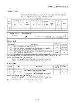
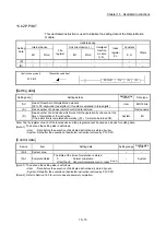
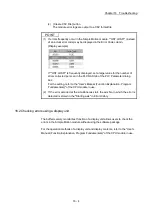
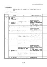
(b) Error and Solution, Intelligent Module Information
• Error and Solution
Details of the selected in the "Error History List" and its corrective action
are displayed.
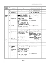
• Intelligent Module Information
The status of Simple Motion module when the error selected in the "Error
History List" occurred is displayed.
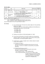
Item Description
Start axis
The axis No. requested to start is stored.
Positioning start No.
The start No. at positioning start is stored.
(Note-1)
Axis in which the error occurred
The axis No. in which the error occurred is stored.
Axis error occurrence (Data No.)
The positioning data No. currently being executed in which the error occurred is stored.
(Note-1), (Note-2)
Current feed value
The current feed value of the axis in which the error occurred (at error occurrence) is
stored.
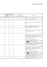
State of the input signal [X0 to XF]
The status of input signals [X0 to XF] (at error occurrence) is stored (in binary).
State of the input signal [X10 to X1F]
The status of input signals [X10 to X1F] (at error occurrence) is stored (in binary).
State of the output signal [Y0 to YF]
The status of output signals [Y0 to YF] (at error occurrence) is stored (in binary).
State of the output signal [Y10 to Y1F]
The status of output signals [Y10 to Y1F] (at error occurrence) is stored (in binary).
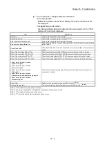
• Axis in which the error occurred
(Upper limit signal)
• Axis in which the error occurred
(Lower limit signal)
• Axis in which the error occurred
(Stop signal)
• Axis in which the error occurred
(External command signal/switching signal)
• Axis in which the error occurred
(Near-point signal)
The status of external input signals of the axis in which the error occurred (at error
occurrence) is stored.
Servo alarm
The alarm code detected by servo amplifier is stored.
(Note-3)
Driver operation alarm
The driver operation alarm detected by servo amplifier is stored.
(Note-4)
(Note-1): "0" is stored at the servo alarm occurrence.
(Note-2): The current cam data No. is displayed for output axis of synchronous control.
(Note-3): "0" is stored unless the servo alarm occurs.
(Note-4): "0" is stored unless the driver operation alarm occurs.
Summary of Contents for MELSEC-L Series
Page 2: ......
Page 30: ...MEMO ...
Page 70: ...2 10 Chapter 2 System Configuration MEMO ...
Page 83: ...3 13 Chapter 3 Specifications and Functions MEMO ...
Page 103: ...3 33 Chapter 3 Specifications and Functions MEMO ...
Page 107: ...3 37 Chapter 3 Specifications and Functions MEMO ...
Page 111: ...3 41 Chapter 3 Specifications and Functions MEMO ...
Page 115: ...3 45 Chapter 3 Specifications and Functions MEMO ...
Page 140: ...4 22 Chapter 4 Installation Wiring and Maintenance of the Product MEMO ...
Page 253: ...5 113 Chapter 5 Data Used for Positioning Control MEMO ...
Page 342: ...5 202 Chapter 5 Data Used for Positioning Control MEMO ...
Page 438: ...7 20 Chapter 7 Memory Configuration and Data Process MEMO ...
Page 440: ...MEMO ...
Page 485: ...9 25 Chapter 9 Major Positioning Control MEMO ...
Page 594: ...9 134 Chapter 9 Major Positioning Control MEMO ...
Page 624: ...10 30 Chapter 10 High Level Positioning Control MEMO ...
Page 656: ...11 32 Chapter 11 Manual Control MEMO ...
Page 690: ...12 34 Chapter 12 Expansion Control MEMO ...
Page 798: ...13 108 Chapter 13 Control Sub Functions MEMO ...
Page 866: ...14 68 Chapter 14 Common Functions MEMO ...
Page 884: ...15 18 Chapter 15 Dedicated Instructions MEMO ...
Page 899: ...16 15 Chapter 16 Troubleshooting MEMO ...
Page 1036: ...Appendix 88 Appendices MEMO ...
Page 1039: ......


