


16 - 14
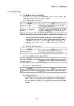
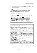
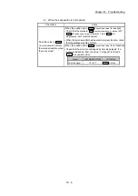
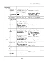
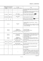
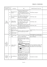
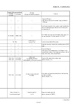
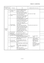
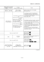
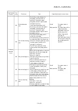
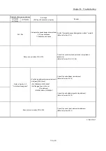
Chapter 16 Troubleshooting
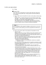
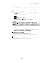
[3] Resetting errors and warnings
Remove the cause of error or warning following the actions described in Section
16.5 and 16.6, before cancel an error or warning state by resetting the error.
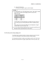
How to clear errors or warnings
An error or warning state is canceled after the following processing has been
carried out by setting "1" in the address of the buffer memory for resetting axis
error (
Cd.5
Axis error reset
).
Axis error detection signal is turned OFF.
"
Md.23
Axis error No."
is cleared.
"
Md.24
Axis warning No.
" is cleared.
"
Md.26
Axis operation status
" is changed from "Error" to "Standby".
"Axis warning detection (
Md.31
Status
: b9)" is turned OFF.
POINT
When servo alarms cannot be reset even if error reset is requested, "0" is not
stored in "
Cd.5
Axis error reset
" by Simple Motion module. It remains "1". Set "0" in
"
Cd.5
Axis error reset
" and then set "1" to execute the error reset again by user side.
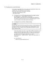
[4] Confirming the error and warning definitions
The error and warning definitions can be confirmed with the error codes and
warning codes. Confirming them requires GX Works2.
Confirming the error definitions
System monitor of GX Works2 (Refer to Section 16.1.)
Error history screen of GX Works2 (Simple Motion Module Setting Tool)
(Refer to the Simple Motion Module Setting Tool Help.)
Confirming the warning definitions
Warning history screen of GX Works2 (Simple Motion Module Setting Tool)
(Refer to the Simple Motion Module Setting Tool Help.)
Summary of Contents for MELSEC-L Series
Page 2: ......
Page 30: ...MEMO ...
Page 70: ...2 10 Chapter 2 System Configuration MEMO ...
Page 83: ...3 13 Chapter 3 Specifications and Functions MEMO ...
Page 103: ...3 33 Chapter 3 Specifications and Functions MEMO ...
Page 107: ...3 37 Chapter 3 Specifications and Functions MEMO ...
Page 111: ...3 41 Chapter 3 Specifications and Functions MEMO ...
Page 115: ...3 45 Chapter 3 Specifications and Functions MEMO ...
Page 140: ...4 22 Chapter 4 Installation Wiring and Maintenance of the Product MEMO ...
Page 253: ...5 113 Chapter 5 Data Used for Positioning Control MEMO ...
Page 342: ...5 202 Chapter 5 Data Used for Positioning Control MEMO ...
Page 438: ...7 20 Chapter 7 Memory Configuration and Data Process MEMO ...
Page 440: ...MEMO ...
Page 485: ...9 25 Chapter 9 Major Positioning Control MEMO ...
Page 594: ...9 134 Chapter 9 Major Positioning Control MEMO ...
Page 624: ...10 30 Chapter 10 High Level Positioning Control MEMO ...
Page 656: ...11 32 Chapter 11 Manual Control MEMO ...
Page 690: ...12 34 Chapter 12 Expansion Control MEMO ...
Page 798: ...13 108 Chapter 13 Control Sub Functions MEMO ...
Page 866: ...14 68 Chapter 14 Common Functions MEMO ...
Page 884: ...15 18 Chapter 15 Dedicated Instructions MEMO ...
Page 899: ...16 15 Chapter 16 Troubleshooting MEMO ...
Page 1036: ...Appendix 88 Appendices MEMO ...
Page 1039: ......


