


16 - 6
Chapter 16 Troubleshooting
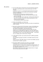
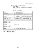
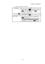
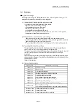
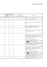
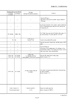
(2) Troubleshooting when a motor does not rotate
Check items and corrective actions for troubleshooting when a motor does not
rotate are described below.
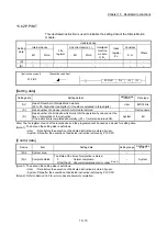
POINT
The following signals must be ON for the Simple Motion module to operate
(excluding when the "positioning test function" of GX Works2 is used).
• READY signal [X0]
• Servo READY signal
• Upper limit signal and Lower limit signal
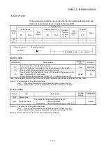
The ON status of signals can be checked by the following monitor data.
• Servo READY signal: "
Md.108
Servo status (high-order buffer memory address)
"
(b0,
b1).
• Upper limit signal and Lower limit signal: "
Md.30
External input signal
" (b0, b1).
Buffer memory address (high-order)
LD77MS2/LD77MS4
LD77MS16
Md.108
Servo status: b0, b1
877+100n 2477+100n
n: Axis No.-1
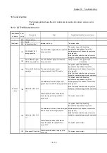
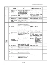
Check item
Action
Is the PLC READY signal turned
ON?
Review the program to turn ON the PLC READY signal.
Is the servo amplifier powered ON? Power on the servo amplifier.
Is there an error in the servo
amplifier?
Check the error code of the servo amplifier and take a
corrective action.
Is the wiring between the Simple
Motion module and servo amplifier
correct?
Check the wiring between the Simple Motion module
and servo amplifier, and correct it.
Is the wiring between the servo
amplifier and motor correct?
Check the wiring between the servo amplifier and motor,
and correct it.
Is the wiring of the limit signal
correct?
Check the wiring and logic setting of the limit signal, and
correct the wiring.
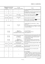
Is there an error in the Simple
Motion module? (
ERR. LED
is on or
flashing)
Check the error code and take a corrective action.
Isn't the value in "
Md.26
Axis
operation status
" "1: stopped"?
• Review the stop program.
• Review whether the stop signal (STOP) is not input
erroneously.
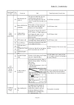
Is the value in "
Md.20
Current feed
value
" changed after positioning
control is performed?
Review the start program.
Is the cumulative pulse of servo
amplifier changed after positioning
control is performed?
Refer to each servo amplifier instruction manual and
check that the function to suppress the motor rotation
is not working.
If a motor does not rotate even after the above items are checked, the possible
cause is a hardware failure.
Please consult your local Mitsubishi representative, explaining a detailed
description of the problem.
Summary of Contents for MELSEC-L Series
Page 2: ......
Page 30: ...MEMO ...
Page 70: ...2 10 Chapter 2 System Configuration MEMO ...
Page 83: ...3 13 Chapter 3 Specifications and Functions MEMO ...
Page 103: ...3 33 Chapter 3 Specifications and Functions MEMO ...
Page 107: ...3 37 Chapter 3 Specifications and Functions MEMO ...
Page 111: ...3 41 Chapter 3 Specifications and Functions MEMO ...
Page 115: ...3 45 Chapter 3 Specifications and Functions MEMO ...
Page 140: ...4 22 Chapter 4 Installation Wiring and Maintenance of the Product MEMO ...
Page 253: ...5 113 Chapter 5 Data Used for Positioning Control MEMO ...
Page 342: ...5 202 Chapter 5 Data Used for Positioning Control MEMO ...
Page 438: ...7 20 Chapter 7 Memory Configuration and Data Process MEMO ...
Page 440: ...MEMO ...
Page 485: ...9 25 Chapter 9 Major Positioning Control MEMO ...
Page 594: ...9 134 Chapter 9 Major Positioning Control MEMO ...
Page 624: ...10 30 Chapter 10 High Level Positioning Control MEMO ...
Page 656: ...11 32 Chapter 11 Manual Control MEMO ...
Page 690: ...12 34 Chapter 12 Expansion Control MEMO ...
Page 798: ...13 108 Chapter 13 Control Sub Functions MEMO ...
Page 866: ...14 68 Chapter 14 Common Functions MEMO ...
Page 884: ...15 18 Chapter 15 Dedicated Instructions MEMO ...
Page 899: ...16 15 Chapter 16 Troubleshooting MEMO ...
Page 1036: ...Appendix 88 Appendices MEMO ...
Page 1039: ......


