
14 - 65
Chapter 14 Common Functions
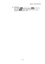
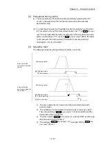
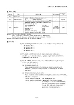
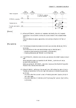
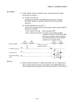
[3] Precautions during control
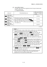
(1) Parameter initialization is only executed when the positioning control is not
carried out (when the PLC READY signal [Y0] is OFF).
The warning "In PLC READY" (warning code: 111) will occur if executed
when the PLC READY signal [Y0] is ON.
(2) Writing to the flash ROM is up to 100,000 times. If writing to the flash ROM
exceeds 100,000 times, the writing may become impossible, and the error
"Flash ROM write error" (error code: 801) will occur.
(3) A "PLC CPU reset" or "PLC CPU power restart" must be carried out after
the parameters are initialized.
Important
Parameter initialization takes about 10 seconds. (Up to 30 seconds are sometimes
required.)
Do not turn the power ON/OFF or reset the PLC CPU during parameter
initialization. If the power is turned OFF or the PLC CPU module is reset to forcibly
end the process, the data backed up in the flash ROM/internal memory
(nonvolatile) will be lost.
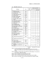
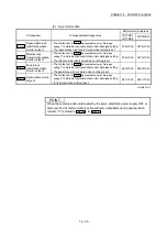
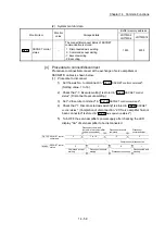
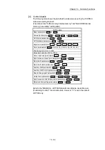
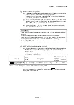
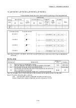
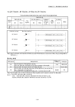
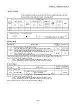
[4] LD77MH initial value setting method
(1) LD77MH initial value setting is carried out by the writing of the data shown in
the table below to the buffer memory using the TO command/intelligent
function device.
The initialization of the parameter is executed at the time point the data is
written to the buffer memory.
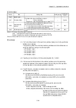
Setting item
Setting
value
Setting details
Buffer memory address
LD77MS2
LD77MS4
LD77MS16
Cd.47
LD77MH initial value
setting request
1
Set "1" (Requests LD77MH initial value setting).
1909
5909
: Refer to Section 5.7.1 "System control data" for details on the setting details.
When the initialization is complete, "0" will be set in "
Cd.47
LD77MH initial value
setting request
" automatically.
Summary of Contents for MELSEC-L Series
Page 2: ......
Page 30: ...MEMO ...
Page 70: ...2 10 Chapter 2 System Configuration MEMO ...
Page 83: ...3 13 Chapter 3 Specifications and Functions MEMO ...
Page 103: ...3 33 Chapter 3 Specifications and Functions MEMO ...
Page 107: ...3 37 Chapter 3 Specifications and Functions MEMO ...
Page 111: ...3 41 Chapter 3 Specifications and Functions MEMO ...
Page 115: ...3 45 Chapter 3 Specifications and Functions MEMO ...
Page 140: ...4 22 Chapter 4 Installation Wiring and Maintenance of the Product MEMO ...
Page 253: ...5 113 Chapter 5 Data Used for Positioning Control MEMO ...
Page 342: ...5 202 Chapter 5 Data Used for Positioning Control MEMO ...
Page 438: ...7 20 Chapter 7 Memory Configuration and Data Process MEMO ...
Page 440: ...MEMO ...
Page 485: ...9 25 Chapter 9 Major Positioning Control MEMO ...
Page 594: ...9 134 Chapter 9 Major Positioning Control MEMO ...
Page 624: ...10 30 Chapter 10 High Level Positioning Control MEMO ...
Page 656: ...11 32 Chapter 11 Manual Control MEMO ...
Page 690: ...12 34 Chapter 12 Expansion Control MEMO ...
Page 798: ...13 108 Chapter 13 Control Sub Functions MEMO ...
Page 866: ...14 68 Chapter 14 Common Functions MEMO ...
Page 884: ...15 18 Chapter 15 Dedicated Instructions MEMO ...
Page 899: ...16 15 Chapter 16 Troubleshooting MEMO ...
Page 1036: ...Appendix 88 Appendices MEMO ...
Page 1039: ......


