

5 - 109
Chapter 5 Data Used for Positioning Control
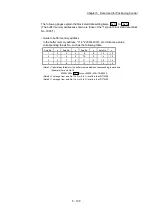
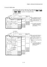
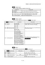
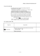
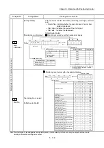
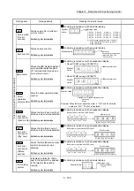
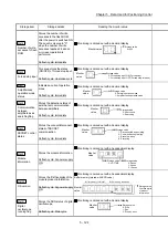
Da.15
Condition target
Set the condition target as required for each control.
Setting value
Setting details
01H : Device X
Set the input/output signal ON/OFF as the conditions.
02H : Device Y
03H : Buffer memory (1-word) Set the value stored in the buffer memory as the condition.
03H: The target buffer memory is "1-word (16 bits)"
04H: The target buffer memory is "2-word (32 bits)"
04H : Buffer memory (2-word)
05H : Positioning data No.
Select only for "simultaneous start".
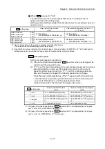
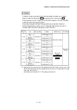
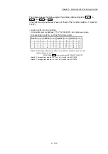
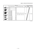
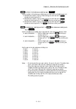
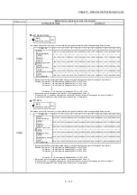
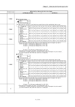
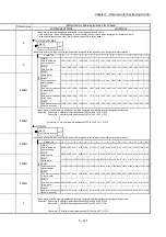
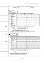
Da.16
Condition operator
Set the condition operator as required for the "
Da.15
Condition target
".
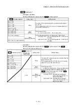
Da.15
Condition target
Setting value
Setting details
01H: Device X
02H: Device Y
07H : DEV=ON
The state (ON/OFF) of an I/O signal is defined as the
condition. Select ON or OFF as the trigger.
08H : DEV=OFF
03H: Buffer memory (1-word)
04H: Buffer memory (2-word)
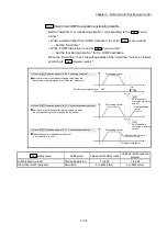
01H :
=P1
Select how to use the value (
) in the buffer memory
as a part of the condition.
02H :
P1
03H :
P1
04H :
P1
05H : P1
P2
06H :
P1, P2
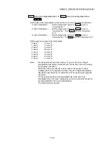
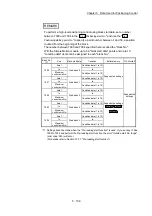
05H: Positioning data No.
10H : Axis 1 selected
If "simultaneous start" is specified, select the axis
(or axes) that should start simultaneously.
LD77MS2
LD77MS4
20H : Axis 2 selected
30H : Axis 1 and 2 selected
40H : Axis 3 selected
50H : Axis 1 and 3 selected
60H : Axis 2 and 3 selected
70H : Axis 1, 2, and 3 selected
80H : Axis 4 selected
90H : Axis 1 and 4 selected
A0H : Axis 2 and 4 selected
B0H : Axis 1, 2, and 4 selected
C0H : Axis 3 and 4 selected
D0H : Axis 1, 3, and 4 selected
E0H : Axis 2, 3, and 4 selected
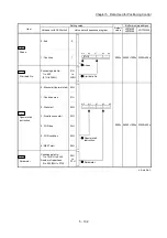
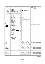
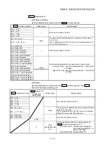
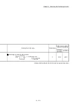
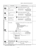
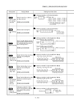
Da.17
Address
Set the address as required for the "
Da.15
Condition target
".
Da.15
Condition target
Setting value
Setting details
01H : Device X
–
Not used. (There is no need to set.)
02H : Device Y
03H : Buffer memory (1-word)
Value
(Buffer memory address)
Set the target "buffer memory address".
(For 2 words, set the low-order buffer memory
address.)
04H : Buffer memory (2-word)
05H : Positioning data No.
–
Not used. (There is no need to set.)
Summary of Contents for MELSEC-L Series
Page 2: ......
Page 30: ...MEMO ...
Page 70: ...2 10 Chapter 2 System Configuration MEMO ...
Page 83: ...3 13 Chapter 3 Specifications and Functions MEMO ...
Page 103: ...3 33 Chapter 3 Specifications and Functions MEMO ...
Page 107: ...3 37 Chapter 3 Specifications and Functions MEMO ...
Page 111: ...3 41 Chapter 3 Specifications and Functions MEMO ...
Page 115: ...3 45 Chapter 3 Specifications and Functions MEMO ...
Page 140: ...4 22 Chapter 4 Installation Wiring and Maintenance of the Product MEMO ...
Page 253: ...5 113 Chapter 5 Data Used for Positioning Control MEMO ...
Page 342: ...5 202 Chapter 5 Data Used for Positioning Control MEMO ...
Page 438: ...7 20 Chapter 7 Memory Configuration and Data Process MEMO ...
Page 440: ...MEMO ...
Page 485: ...9 25 Chapter 9 Major Positioning Control MEMO ...
Page 594: ...9 134 Chapter 9 Major Positioning Control MEMO ...
Page 624: ...10 30 Chapter 10 High Level Positioning Control MEMO ...
Page 656: ...11 32 Chapter 11 Manual Control MEMO ...
Page 690: ...12 34 Chapter 12 Expansion Control MEMO ...
Page 798: ...13 108 Chapter 13 Control Sub Functions MEMO ...
Page 866: ...14 68 Chapter 14 Common Functions MEMO ...
Page 884: ...15 18 Chapter 15 Dedicated Instructions MEMO ...
Page 899: ...16 15 Chapter 16 Troubleshooting MEMO ...
Page 1036: ...Appendix 88 Appendices MEMO ...
Page 1039: ......


