


3 - 22
Chapter 3 Specifications and Functions
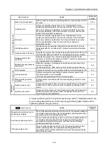
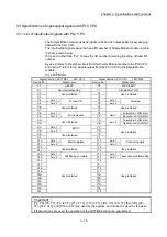
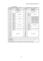
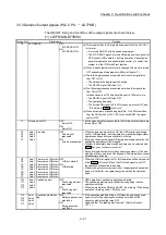
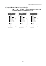
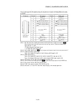
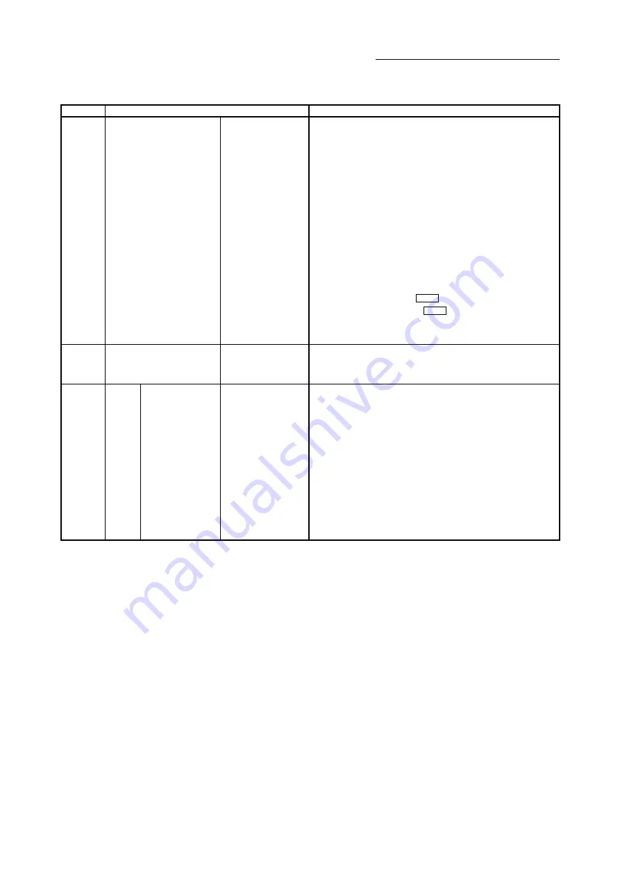
(2) LD77MS16
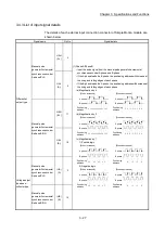
Device No.
Signal name
Details
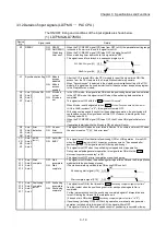
Y0 PLC
READY
OFF:
PLC READY OFF
ON:
PLC READY ON
(a) This signal notifies the Simple Motion module that the PLC CPU
is normal.
• It is turned ON/OFF with the sequence program.
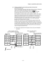
• This signal is turned ON during positioning control, OPR
control, JOG operation, inching operation, manual pulse
generator operation and speed-torque control etc. unless the
system is in the GX Works2 test function.
(b) When the data (parameter etc.) are changed, this signal is turned
OFF depending on the parameter (Refer to Chapter 7.).
(c) The following processes are carried out when this signal turns
from OFF to ON.
• The parameter setting range is checked.
• The READY signal [X0] turns ON.
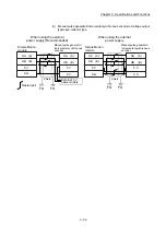
(d) The following processes are carried out when this signal turns
from ON to OFF.
In these cases, the OFF time should be set to 100ms or more.
• The READY signal [X0] turns OFF.
• The operating axis stops.
• The M code ON signal (
Md.31
Status
: b12) for each axis turns
OFF, and "0" is stored in "
Md.25
Valid M code
".
(e) When parameters or positioning data (No. 1 to 600) are written
from the GX Works2 or PLC CPU to the flash ROM, this signal
will turn OFF.
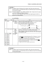
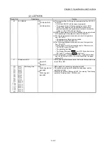
Y1
All axis servo ON
OFF:
Servo OFF
ON:
Servo ON
• All the servo amplifiers connected to the Simple Motion module are
turned ON or OFF.
Y10
Y11
Y12
Y13
Y14
Y15
Y16
Y17
Y18
Y19
Y1A
Y1B
Y1C
Y1D
Y1E
Y1F
Axis 1
Axis 2
Axis 3
Axis 4
Axis 5
Axis 6
Axis 7
Axis 8
Axis 9
Axis 10
Axis 11
Axis 12
Axis 13
Axis 14
Axis 15
Axis 16
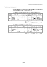
Positioning start
OFF:
Positioning start not
requested
ON:
Positioning start
requested
• OPR operation or positioning operation is started.
• The positioning start signal is valid at the rising edge, and the
operation is started.
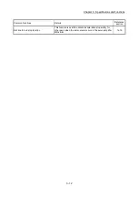
• When this signal turns ON during BUSY, the warning "Start during
operation" (warning code: 100) will occur.
Summary of Contents for MELSEC-L Series
Page 2: ......
Page 30: ...MEMO ...
Page 70: ...2 10 Chapter 2 System Configuration MEMO ...
Page 83: ...3 13 Chapter 3 Specifications and Functions MEMO ...
Page 103: ...3 33 Chapter 3 Specifications and Functions MEMO ...
Page 107: ...3 37 Chapter 3 Specifications and Functions MEMO ...
Page 111: ...3 41 Chapter 3 Specifications and Functions MEMO ...
Page 115: ...3 45 Chapter 3 Specifications and Functions MEMO ...
Page 140: ...4 22 Chapter 4 Installation Wiring and Maintenance of the Product MEMO ...
Page 253: ...5 113 Chapter 5 Data Used for Positioning Control MEMO ...
Page 342: ...5 202 Chapter 5 Data Used for Positioning Control MEMO ...
Page 438: ...7 20 Chapter 7 Memory Configuration and Data Process MEMO ...
Page 440: ...MEMO ...
Page 485: ...9 25 Chapter 9 Major Positioning Control MEMO ...
Page 594: ...9 134 Chapter 9 Major Positioning Control MEMO ...
Page 624: ...10 30 Chapter 10 High Level Positioning Control MEMO ...
Page 656: ...11 32 Chapter 11 Manual Control MEMO ...
Page 690: ...12 34 Chapter 12 Expansion Control MEMO ...
Page 798: ...13 108 Chapter 13 Control Sub Functions MEMO ...
Page 866: ...14 68 Chapter 14 Common Functions MEMO ...
Page 884: ...15 18 Chapter 15 Dedicated Instructions MEMO ...
Page 899: ...16 15 Chapter 16 Troubleshooting MEMO ...
Page 1036: ...Appendix 88 Appendices MEMO ...
Page 1039: ......


