


8 - 16
Chapter 8 OPR Control
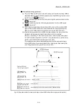
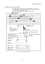
Precautions during operation
(1) The error "Start at OP" (error code: 201) will occur if another machine OPR is
attempted immediately after a machine OPR completion when the OP is in the
near-point dog ON position.
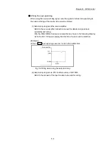
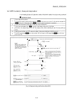
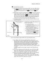
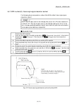
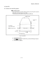
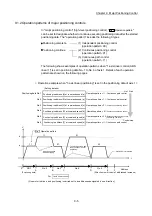
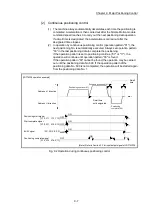
(2) The following shows the operation when a machine OPR is started from the
near-point dog ON position.
Zero signal
Near-point dog
Pr.46 OPR speed
Pr.47 Creep speed
OPR direction
Pr.44
ON
1)
2)
V
3)
OFF
Hardware limit switch
[Operation when a machine OPR is started
from the near-point dog ON position]
1) The machine moves in the opposite direction
against of OPR at the OPR speed.
2) The machine begins decelerating when the
first zero signal is detected.
3) After deceleration stop, the operation moves in
direction of OPR at the creep speed, and then
stops at the zero signal to complete the
machine OPR.
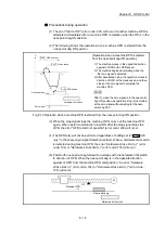
POINT
After 1), when the zero signal is in the near-point
dog ON position, deceleration stop (2)) is started
at the zero signal without waiting for the near-
point dog OFF.
Fig. 8.12 Operation when a machine OPR is started from the near-point dog ON position
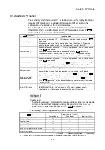
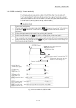
(3) When the stop signal stops the machine OPR, carry out the machine OPR
again. When restart command is turned ON after the stop signal stops the
OPR, the error "OPR restart not possible" (error code: 209) will occur.
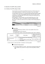
(4) The OPR retry will not be performed regardless of setting set in "
Pr.48
OPR
retry
" in the scale origin signal detection method. When a hardware limit switch
is detected during machine OPR, the error "Hardware stroke limit (+)" (error
code: 104) or "Hardware stroke limit (-)" (error code: 105) will occur.
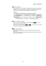
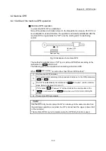
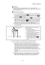
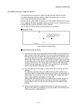
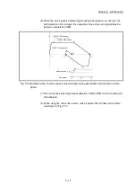
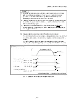
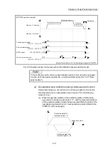
(5) Position the near-point dog forward to overlaps with the hardware limit switch
in direction of OPR. When the near-point dog is in the opposite direction
against of OPR from the machine OPR start position, the error "Hardware
stroke limit (+)" (error code: 104) or "Hardware stroke limit (-)" (error code:
105) will occur.
Machine OPR
Near-point dog
Hardware limit switch
OP
M
Summary of Contents for MELSEC-L Series
Page 2: ......
Page 30: ...MEMO ...
Page 70: ...2 10 Chapter 2 System Configuration MEMO ...
Page 83: ...3 13 Chapter 3 Specifications and Functions MEMO ...
Page 103: ...3 33 Chapter 3 Specifications and Functions MEMO ...
Page 107: ...3 37 Chapter 3 Specifications and Functions MEMO ...
Page 111: ...3 41 Chapter 3 Specifications and Functions MEMO ...
Page 115: ...3 45 Chapter 3 Specifications and Functions MEMO ...
Page 140: ...4 22 Chapter 4 Installation Wiring and Maintenance of the Product MEMO ...
Page 253: ...5 113 Chapter 5 Data Used for Positioning Control MEMO ...
Page 342: ...5 202 Chapter 5 Data Used for Positioning Control MEMO ...
Page 438: ...7 20 Chapter 7 Memory Configuration and Data Process MEMO ...
Page 440: ...MEMO ...
Page 485: ...9 25 Chapter 9 Major Positioning Control MEMO ...
Page 594: ...9 134 Chapter 9 Major Positioning Control MEMO ...
Page 624: ...10 30 Chapter 10 High Level Positioning Control MEMO ...
Page 656: ...11 32 Chapter 11 Manual Control MEMO ...
Page 690: ...12 34 Chapter 12 Expansion Control MEMO ...
Page 798: ...13 108 Chapter 13 Control Sub Functions MEMO ...
Page 866: ...14 68 Chapter 14 Common Functions MEMO ...
Page 884: ...15 18 Chapter 15 Dedicated Instructions MEMO ...
Page 899: ...16 15 Chapter 16 Troubleshooting MEMO ...
Page 1036: ...Appendix 88 Appendices MEMO ...
Page 1039: ......


