


1 - 4
Chapter 1 Product Outline
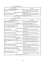
(7) Setting, monitoring, and testing through GX Works2
Parameters and positioning data for the LD77MS can be set using GX Works2
(Simple Motion Module Setting).
Moreover, using the test function of GX Works2 (Simple Motion Module Setting),
users can check the wiring status and the validity of the preset parameters and
positioning data by performing test operation before creating a program for
positioning control.
The control monitor function of GX Works2 allows user to debug programs
efficiently.
The servo parameters can be set easily by using the GX Works2 in combination
with the MR Configurator2.
(8) Compatibility with the LD77MH
The proven programs in LD77MH can be used because the LD77MS is
compatible with the LD77MH.
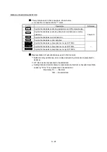
(9) Forced stop function
The batch forced stop is available for all axes of servo amplifier by the forced
stop signal.
"Valid/Invalid" of the forced stop input signal can be selected by the parameters.
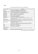
(10) Connection between the LD77MS and servo amplifier with high
speed synchronous network by SSCNET (/H)
The LD77MS can be directly connected to the Mitsubishi servo amplifiers of
MR-J4-B/MR-J3-B series using the SSCNET (/H). Also, it can be directly
connected to the Mitsubishi servo amplifiers of MR-JE-B series using the
SSCNET /H.
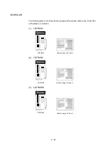
(a) Because the high speed synchronous network by SSCNET (/H) is used
to connect the LD77MS and the servo amplifier, or servo amplifiers, saving
wiring can be realized. The maximum distance between the LD77MS and
servo amplifier, servo amplifier and servo amplifier of the SSCNET cable
on the same bus was set to 50(164.04) [m(ft.)] (SSCNET )/100(328.08)
[m(ft.)] (SSCNET /H) and the flexibility will improve at the system design.
(b) By the use of SSCNET cable (Optical communication), influence of
electromagnetic noise and others from servo amplifier, etc. are reduced.
(c) The servo parameters can be set on the LD77MS side to write or read
them to/from the servo amplifier using the SSCNET communication.
(d) The actual current value and error description contained in the servo can
be checked by the buffer memory of the LD77MS.
(e) The communication between the MR Configurator2 and servo amplifiers is
possible via the PLC CPU.
Summary of Contents for MELSEC-L Series
Page 2: ......
Page 30: ...MEMO ...
Page 70: ...2 10 Chapter 2 System Configuration MEMO ...
Page 83: ...3 13 Chapter 3 Specifications and Functions MEMO ...
Page 103: ...3 33 Chapter 3 Specifications and Functions MEMO ...
Page 107: ...3 37 Chapter 3 Specifications and Functions MEMO ...
Page 111: ...3 41 Chapter 3 Specifications and Functions MEMO ...
Page 115: ...3 45 Chapter 3 Specifications and Functions MEMO ...
Page 140: ...4 22 Chapter 4 Installation Wiring and Maintenance of the Product MEMO ...
Page 253: ...5 113 Chapter 5 Data Used for Positioning Control MEMO ...
Page 342: ...5 202 Chapter 5 Data Used for Positioning Control MEMO ...
Page 438: ...7 20 Chapter 7 Memory Configuration and Data Process MEMO ...
Page 440: ...MEMO ...
Page 485: ...9 25 Chapter 9 Major Positioning Control MEMO ...
Page 594: ...9 134 Chapter 9 Major Positioning Control MEMO ...
Page 624: ...10 30 Chapter 10 High Level Positioning Control MEMO ...
Page 656: ...11 32 Chapter 11 Manual Control MEMO ...
Page 690: ...12 34 Chapter 12 Expansion Control MEMO ...
Page 798: ...13 108 Chapter 13 Control Sub Functions MEMO ...
Page 866: ...14 68 Chapter 14 Common Functions MEMO ...
Page 884: ...15 18 Chapter 15 Dedicated Instructions MEMO ...
Page 899: ...16 15 Chapter 16 Troubleshooting MEMO ...
Page 1036: ...Appendix 88 Appendices MEMO ...
Page 1039: ......


