
9 - 124
Chapter 9 Major Positioning Control
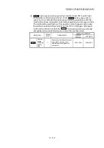
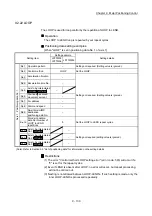
[2] Changing to a new current value using the current value changing
start No. (No. 9003)
In "current value changing" ("
Cd.3
Positioning start No." = 9003), "
Md.20
Current feed value" is changed to the address set in "
Cd.9
New current value".
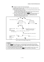
Operation chart
The current value is changed by setting the new current value in the current value
changing buffer memory "
Cd.9
New current value
", setting "9003" in the "
Cd.3
Positioning start No.
", and turning ON the positioning start signal.
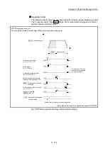
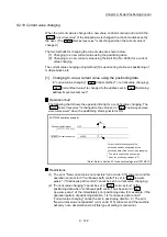
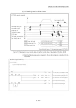
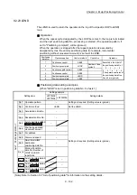
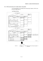
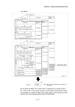
[LD77MS4 operation example]
Positioning start signal
Md.20 Current feed value
50000
0
OFF
ON
Current value changes to the
positioning address designated by
the current value changing buffer memory.
The above chart shows an example
when the positioning address is "0".
[Y10, Y11, Y12, Y13]
(Note): Refer to Section 3.3 for input/output signal of LD77MS16.
Restrictions
(1) The error "Outside new current value range" (error code: 514) will occur if the
designated value is outside the setting range when "degree" is set in "Unit
setting".
(2) The error "Software stroke limit +" (error code: 507) or "Software stroke limit -"
(error code: 508) will occur if the designated value is outside the software
stroke limit range.
(3) The current value cannot be changed during stop commands and while the M
code ON signal is ON.
(4) The M code output function is made invalid.
POINTS
The current value can be changed using the current value changing start No. (No. 9003) if "0:
Positioning control is not executed" is set in "
Pr.55
Operation setting for incompletion of OPR" and
OPR request flag is ON.
Summary of Contents for MELSEC-L Series
Page 2: ......
Page 30: ...MEMO ...
Page 70: ...2 10 Chapter 2 System Configuration MEMO ...
Page 83: ...3 13 Chapter 3 Specifications and Functions MEMO ...
Page 103: ...3 33 Chapter 3 Specifications and Functions MEMO ...
Page 107: ...3 37 Chapter 3 Specifications and Functions MEMO ...
Page 111: ...3 41 Chapter 3 Specifications and Functions MEMO ...
Page 115: ...3 45 Chapter 3 Specifications and Functions MEMO ...
Page 140: ...4 22 Chapter 4 Installation Wiring and Maintenance of the Product MEMO ...
Page 253: ...5 113 Chapter 5 Data Used for Positioning Control MEMO ...
Page 342: ...5 202 Chapter 5 Data Used for Positioning Control MEMO ...
Page 438: ...7 20 Chapter 7 Memory Configuration and Data Process MEMO ...
Page 440: ...MEMO ...
Page 485: ...9 25 Chapter 9 Major Positioning Control MEMO ...
Page 594: ...9 134 Chapter 9 Major Positioning Control MEMO ...
Page 624: ...10 30 Chapter 10 High Level Positioning Control MEMO ...
Page 656: ...11 32 Chapter 11 Manual Control MEMO ...
Page 690: ...12 34 Chapter 12 Expansion Control MEMO ...
Page 798: ...13 108 Chapter 13 Control Sub Functions MEMO ...
Page 866: ...14 68 Chapter 14 Common Functions MEMO ...
Page 884: ...15 18 Chapter 15 Dedicated Instructions MEMO ...
Page 899: ...16 15 Chapter 16 Troubleshooting MEMO ...
Page 1036: ...Appendix 88 Appendices MEMO ...
Page 1039: ......


