


7 - 6
Chapter 7 Memory Configuration and Data Process
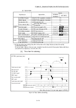
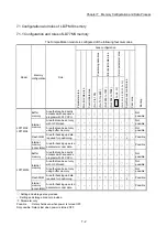
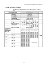
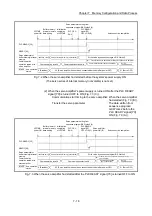
Buffer memory area configuration
Buffer memory address
*1
Writing
possibility
LD77MS2/LD77MS4 LD77MS16
Servo parameter area
Servo series
30100+200n 28400+100n
Possible
PA group
PA01 to PA18
30101+200n to 30118+200n
28401+100n to 28418+100n
PA19
30932+50n
Set with GX Works2
PA20 to PA32
64400+250n to 64412+250n
64400+70n to 64412+70n
PB group
30119+200n to 30163+200n
28419+100n to 28463+100n
64413+250n to 64431+250n
64413+70n to 64431+70n
PC group
30164+200n to 30195+200n
28464+100n to 28495+100n
64432+250n to 64463+250n
64432+70n to 64463+70n
PD group
30196+200n to 30227+200n
Set with GX Works2
64464+250n to 64479+250n
PE group
30228+200n to 30267+200n
64480+250n to 64503+250n
PS group
30268+200n to 30299+200n
PF group
30900+50n to 30915+50n
64504+250n to 64535+250n
Po group
30916+50n to 30931+50n
64536+250n to 64551+250n
PL group
64552+250n to 64599+250n
Synchronous control
area
*2
Servo input axis parameter
32800+10n to 32805+10n
Possible
Servo input axis monitor data
33120+10n to 33127+10n
Not possible
Synchronous encoder axis
parameter
34720+20j to 34735+20j
Possible
Synchronous encoder axis control
data
35040+10j to 35047+10j
Possible
Synchronous encoder axis
monitor data
35200+20j to 35212+20j
Not possible
Synchronous control system
control data
36320, 36322
Possible
Synchronous parameter
36400+200n to 36513+200n
Possible
Synchronous control monitor data
42800+40n to 42835+40n
Not possible
Control data for synchronous
control
44080+20n to 44090+20n
Possible
Cam operation control data
45000 to 53791
Possible
Cam operation monitor data
53800 to 53801
Not possible
n: Axis No.-1
k: Mark detection setting No.-1
j: Synchronous encoder axis No.-1
1: Use of address Nos. skipped above is prohibited. If used, the system may not operate correctly.
2: Refer to "MELSEC-Q/L QD77MS/QD77GF/LD77MS/LD77MH Simple Motion Module User's Manual
(Synchronous Control)" for details.
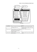
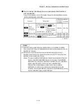
POINT
When the parameter of the servo amplifier side is changed by the following
method, the Simple Motion module reads parameters automatically, and the data
is transmitted to the servo parameter area in the buffer memory/internal memory
and internal memory (nonvolatile).
(1) When changing the servo parameters by the auto tuning.
(2) When the servo parameter is changing after the MR Configurator2 is connected
directly with the servo amplifier.
Summary of Contents for MELSEC-L Series
Page 2: ......
Page 30: ...MEMO ...
Page 70: ...2 10 Chapter 2 System Configuration MEMO ...
Page 83: ...3 13 Chapter 3 Specifications and Functions MEMO ...
Page 103: ...3 33 Chapter 3 Specifications and Functions MEMO ...
Page 107: ...3 37 Chapter 3 Specifications and Functions MEMO ...
Page 111: ...3 41 Chapter 3 Specifications and Functions MEMO ...
Page 115: ...3 45 Chapter 3 Specifications and Functions MEMO ...
Page 140: ...4 22 Chapter 4 Installation Wiring and Maintenance of the Product MEMO ...
Page 253: ...5 113 Chapter 5 Data Used for Positioning Control MEMO ...
Page 342: ...5 202 Chapter 5 Data Used for Positioning Control MEMO ...
Page 438: ...7 20 Chapter 7 Memory Configuration and Data Process MEMO ...
Page 440: ...MEMO ...
Page 485: ...9 25 Chapter 9 Major Positioning Control MEMO ...
Page 594: ...9 134 Chapter 9 Major Positioning Control MEMO ...
Page 624: ...10 30 Chapter 10 High Level Positioning Control MEMO ...
Page 656: ...11 32 Chapter 11 Manual Control MEMO ...
Page 690: ...12 34 Chapter 12 Expansion Control MEMO ...
Page 798: ...13 108 Chapter 13 Control Sub Functions MEMO ...
Page 866: ...14 68 Chapter 14 Common Functions MEMO ...
Page 884: ...15 18 Chapter 15 Dedicated Instructions MEMO ...
Page 899: ...16 15 Chapter 16 Troubleshooting MEMO ...
Page 1036: ...Appendix 88 Appendices MEMO ...
Page 1039: ......


