

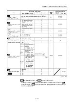

5 - 37
Chapter 5 Data Used for Positioning Control
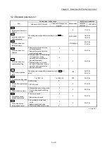
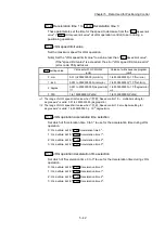
Pr.80
External input signal selection
Set whether to use "external input signal of servo amplifier" or "buffer memory of
LD77MS" as an external input signal (upper/lower limit signal or near-point dog
signal)".
1: External input signal of servo amplifier
*1
2: Buffer memory of LD77MS
1: At MR-JE-B use, refer to Appendix 6.5 "Connection with MR-JE-B".
POINT
(1) When other than "1: External input signal of servo amplifier" and "2: Buffer
memory of LD77MS" is set, the error "External input signal selection error"
(error code: 936) occurs at turning the PLC READY signal [Y0] ON, and the
READY signal [X0] is not turned ON.
(2) When "2: Buffer memory of LD77MS" is set, operation is affected by the PLC
scan time.
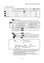
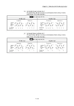
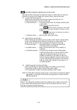
Pr.24
Manual pulse generator/Incremental synchronous encoder input
selection
Set the manual pulse generator/incremental synchronous encoder input pulse
mode. (Only the value specified against the axis 1 is valid.)
0: A-phase/B-phase multiplied by 4
1: A-phase/B-phase multiplied by 2
2: A-phase/B-phase multiplied by 1
3: PLS/SIGN
Set the positive logic or negative logic in "
Pr.22
Input signal logic selection
".
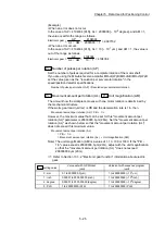
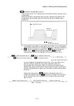
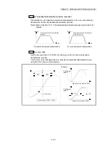
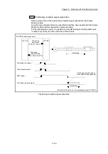
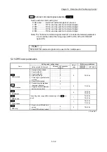
(1) A-phase/B-phase mode
• When the A-phase is 90° ahead of the B-phase, the motor will forward run.
• When the B-phase is 90° ahead of the A-phase, the motor will reverse run.
(a) A-phase/B-phase multiplied by 4
The positioning address increases or decreases at rising or falling edges
of A-phase/B-phase.
Pr.22
Input signal logic selection
Positive logic
Negative logic
+1
Reverse run
Forward run
A-phase
(A )
B-phase
(B )
+1+1+1+1+1+1+1
-1 -1 -1 -1 -1 -1 -1 -1
Positioning
address
+1
Reverse run
Forward run
A-phase
(A )
B-phase
(B )
+1+1+1+1+1+1+1
-1 -1 -1 -1 -1 -1 -1 -1
Positioning
address
Summary of Contents for MELSEC-L Series
Page 2: ......
Page 30: ...MEMO ...
Page 70: ...2 10 Chapter 2 System Configuration MEMO ...
Page 83: ...3 13 Chapter 3 Specifications and Functions MEMO ...
Page 103: ...3 33 Chapter 3 Specifications and Functions MEMO ...
Page 107: ...3 37 Chapter 3 Specifications and Functions MEMO ...
Page 111: ...3 41 Chapter 3 Specifications and Functions MEMO ...
Page 115: ...3 45 Chapter 3 Specifications and Functions MEMO ...
Page 140: ...4 22 Chapter 4 Installation Wiring and Maintenance of the Product MEMO ...
Page 253: ...5 113 Chapter 5 Data Used for Positioning Control MEMO ...
Page 342: ...5 202 Chapter 5 Data Used for Positioning Control MEMO ...
Page 438: ...7 20 Chapter 7 Memory Configuration and Data Process MEMO ...
Page 440: ...MEMO ...
Page 485: ...9 25 Chapter 9 Major Positioning Control MEMO ...
Page 594: ...9 134 Chapter 9 Major Positioning Control MEMO ...
Page 624: ...10 30 Chapter 10 High Level Positioning Control MEMO ...
Page 656: ...11 32 Chapter 11 Manual Control MEMO ...
Page 690: ...12 34 Chapter 12 Expansion Control MEMO ...
Page 798: ...13 108 Chapter 13 Control Sub Functions MEMO ...
Page 866: ...14 68 Chapter 14 Common Functions MEMO ...
Page 884: ...15 18 Chapter 15 Dedicated Instructions MEMO ...
Page 899: ...16 15 Chapter 16 Troubleshooting MEMO ...
Page 1036: ...Appendix 88 Appendices MEMO ...
Page 1039: ......


