


14 - 44
Chapter 14 Common Functions
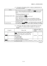
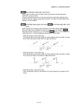
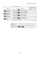
POINT
When "1: Valid" is set in "
Pr.114
External command signal compensation valid/invalid
setting
", the response time of the high-speed input signal is compensated and the
latch accuracy will be enhanced.
(For details of "
Pr.114
External command signal compensation valid/invalid setting
",
refer to Section 5.2.7 "Expansion parameters".)
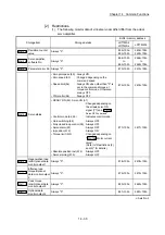
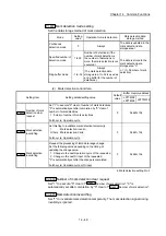
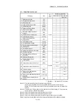
[3] List of buffer memory
The following shows the configuration of buffer memory for mark detection
function.
Buffer memory
address
Number of
word
Item
Mark detection setting No.
54000 to 54019
20
Mark detection setting parameter
Pr.800
to
Pr.807
Mark detection setting 1
54020 to 54039
20
Mark detection setting 2
54040 to 54059
20
Mark detection setting 3
to
to
to
54300 to 54319
20
Mark detection setting 16
54640 to 54649
10
Mark detection control data
Cd.800
,
Cd.801
,
Cd.802
Mark detection setting 1
54650 to 54659
10
Mark detection setting 2
54660 to 54669
10
Mark detection setting 3
to
to
to
54790 to 54799
10
Mark detection setting 16
54960 to 55039
80
Mark detection monitor data
Md.800
,
Md.801
Mark detection setting 1
55040 to 55119
80
Mark detection setting 2
55120 to 55199
80
Mark detection setting 3
to
to
to
56160 to 56239
80
Mark detection setting 16
(Note): Refer to the table of "Performance specifications" in this section for the range of mark
detection setting No. that can be used for each module.
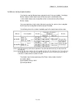
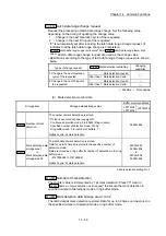
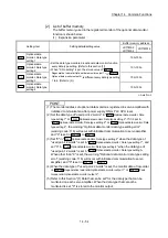
• Guide to buffer memory address
In the buffer memory address, "k" in "54002+20k", etc. indicates a value
corresponding to mark detection setting No. such as the following table.
Mark detection
setting No.
k
Mark detection
setting No.
k
Mark detection
setting No.
k
Mark detection
setting No.
k
1 0 5 4 9 8 13 12
2 1 6 5 10 9 14 13
3 2 7 6 11 10 15 14
4 3 8 7 12 11 16 15
(Note): Refer to the table of "Performance specifications" in this section for the range of mark
detection setting No. that can be used for each module.
(Note): Calculate as follows for the buffer memory address corresponding to each mark detection
setting No.
(Example) For mark detection setting 16
54002+20k (
Pr.802
Mark detection data type
)=54002+20 15=54302
(Note): The range from mark detection setting No.1 to 4 (k=0 to 3) is valid in the
LD77MS2/LD77MS4.
Summary of Contents for MELSEC-L Series
Page 2: ......
Page 30: ...MEMO ...
Page 70: ...2 10 Chapter 2 System Configuration MEMO ...
Page 83: ...3 13 Chapter 3 Specifications and Functions MEMO ...
Page 103: ...3 33 Chapter 3 Specifications and Functions MEMO ...
Page 107: ...3 37 Chapter 3 Specifications and Functions MEMO ...
Page 111: ...3 41 Chapter 3 Specifications and Functions MEMO ...
Page 115: ...3 45 Chapter 3 Specifications and Functions MEMO ...
Page 140: ...4 22 Chapter 4 Installation Wiring and Maintenance of the Product MEMO ...
Page 253: ...5 113 Chapter 5 Data Used for Positioning Control MEMO ...
Page 342: ...5 202 Chapter 5 Data Used for Positioning Control MEMO ...
Page 438: ...7 20 Chapter 7 Memory Configuration and Data Process MEMO ...
Page 440: ...MEMO ...
Page 485: ...9 25 Chapter 9 Major Positioning Control MEMO ...
Page 594: ...9 134 Chapter 9 Major Positioning Control MEMO ...
Page 624: ...10 30 Chapter 10 High Level Positioning Control MEMO ...
Page 656: ...11 32 Chapter 11 Manual Control MEMO ...
Page 690: ...12 34 Chapter 12 Expansion Control MEMO ...
Page 798: ...13 108 Chapter 13 Control Sub Functions MEMO ...
Page 866: ...14 68 Chapter 14 Common Functions MEMO ...
Page 884: ...15 18 Chapter 15 Dedicated Instructions MEMO ...
Page 899: ...16 15 Chapter 16 Troubleshooting MEMO ...
Page 1036: ...Appendix 88 Appendices MEMO ...
Page 1039: ......


