

10 - 17
Chapter 10 High-Level Positioning Control
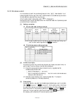
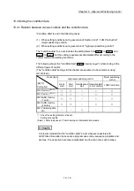
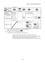
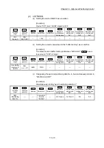
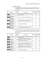
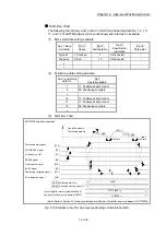
The setting requirements and details of the following "condition data"
Da.16
to
Da.19
and
Da.23
setting items differ according to the "
Da.15
Condition target
" setting.
The following shows the
Da.16
to
Da.19
and
Da.23
setting items corresponding to
the "
Da.15
Condition target
".
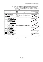
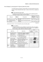
• LD77MS2/LD77MS4
Other setting
item
Da.15
Condition target
Da.16
Condition operator
Da.17
Address
Da.18
Parameter 1
Da.19
Parameter 2
01H: Device X
07H: DEV=ON
08H: DEV=OFF
–
X: 0H, 1H, 4H to 17H
Y: 0H, 1H, 4H to 17H
–
02H: Device Y
03H: Buffer memory
(1 word)
(Note-1)
01H:
=P1
02H:
P1
03H:
P1
04H:
P1
05H: P1
P2
06H:
P1, P2
Buffer
memory
address
P1 (numeric value)
P2 (numeric value)
(Set only when "
Da.16
" is
[05H] or [06H].)
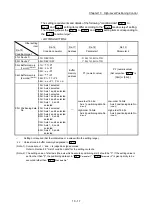
04H: Buffer memory
(2 words)
(Note-1)
05H: Positioning data
No.
10H: Axis 1 selected
20H: Axis 2 selected
30H: Axis 1 and 2 selected
40H: Axis 3 selected
50H: Axis 1 and 3 selected
60H: Axis 2 and 3 selected
70H: Axis 1, 2, and 3
selected
80H: Axis 4 selected
90H: Axis 1 and 4 selected
A0H: Axis 2 and 4 selected
B0H: Axis 1, 2, and 4
selected
C0H: Axis 3 and 4 selected
D0H: Axis 1, 3, and 4
selected
E0H: Axis 2, 3, and 4
selected
—
Low-order 16 bits:
Axis 1 positioning data No.
(Note-2)
High-order 16 bits:
Axis 2 positioning data No.
(Note-2)
Low-order 16 bits:
Axis 3 positioning data No.
(Note-2)
High-order 16 bits:
Axis 4 positioning data No.
(Note-2)
–
: Setting not required (Set the initial value or a value within the setting range.)
: Value stored in buffer memory designated in
Da.17
(Note-1): Comparison of
and
is judged as signed values.
Refer to Section 5.5 "List of condition data" for the setting contents.
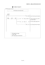
(Note-2): The setting value of start axis (the axis which executes positioning start) should be "0". If the setting value is
set to other than "0", the positioning data set in "
Da.18
Parameter 1
", "
Da.19
Parameter 2
" is given priority to be
executed rather than "
Da.12
Start data No.
".
Summary of Contents for MELSEC-L Series
Page 2: ......
Page 30: ...MEMO ...
Page 70: ...2 10 Chapter 2 System Configuration MEMO ...
Page 83: ...3 13 Chapter 3 Specifications and Functions MEMO ...
Page 103: ...3 33 Chapter 3 Specifications and Functions MEMO ...
Page 107: ...3 37 Chapter 3 Specifications and Functions MEMO ...
Page 111: ...3 41 Chapter 3 Specifications and Functions MEMO ...
Page 115: ...3 45 Chapter 3 Specifications and Functions MEMO ...
Page 140: ...4 22 Chapter 4 Installation Wiring and Maintenance of the Product MEMO ...
Page 253: ...5 113 Chapter 5 Data Used for Positioning Control MEMO ...
Page 342: ...5 202 Chapter 5 Data Used for Positioning Control MEMO ...
Page 438: ...7 20 Chapter 7 Memory Configuration and Data Process MEMO ...
Page 440: ...MEMO ...
Page 485: ...9 25 Chapter 9 Major Positioning Control MEMO ...
Page 594: ...9 134 Chapter 9 Major Positioning Control MEMO ...
Page 624: ...10 30 Chapter 10 High Level Positioning Control MEMO ...
Page 656: ...11 32 Chapter 11 Manual Control MEMO ...
Page 690: ...12 34 Chapter 12 Expansion Control MEMO ...
Page 798: ...13 108 Chapter 13 Control Sub Functions MEMO ...
Page 866: ...14 68 Chapter 14 Common Functions MEMO ...
Page 884: ...15 18 Chapter 15 Dedicated Instructions MEMO ...
Page 899: ...16 15 Chapter 16 Troubleshooting MEMO ...
Page 1036: ...Appendix 88 Appendices MEMO ...
Page 1039: ......


