


9 - 63
Chapter 9 Major Positioning Control
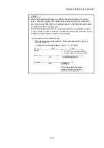
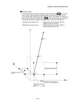
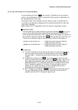
Restrictions
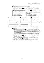
(1) 2-axis circular interpolation control cannot be set in the following cases.
When "degree" is set in "
Pr.1
Unit setting
"
When the units set in "
Pr.1
Unit setting
" are different for the reference axis and
interpolation axis. ("mm" and "inch" combinations are possible.)
When "reference axis speed" is set in "
Pr.20
Interpolation speed designation
method
"
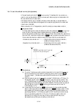
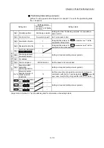
(2) An error will occur and the positioning start will not be possible in the following
cases. The machine will immediately stop if the error is detected during
positioning control.
When the radius exceeds "536870912 (=2
29
)". (The maximum radius for
which circular interpolation control is possible is "536870912 (=2
29
)"
... The error "Outside radius range" (error code: 544) will occur at
positioning start.
When the center point address is outside the range of "–2147483648 (–2
31
) to
2147483647 (2
31
–1)"
... The error "Sub point setting error" (error code: 525) will occur at
positioning start.
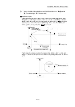
When the start point address is the same as the end point address
... The error "End point setting error" (error code: 526) will occur.
When the start point address is the same as the sub point address
... The error "Sub point setting error" (error code: 525) will occur.
When the end point address is the same as the sub point address
... The error "Sub point setting error" (error code: 525) will occur.
When the start point address, sub point address, and end point address are in
a straight line
... The error "Sub point setting error" (error code: 525) will occur.
Summary of Contents for MELSEC-L Series
Page 2: ......
Page 30: ...MEMO ...
Page 70: ...2 10 Chapter 2 System Configuration MEMO ...
Page 83: ...3 13 Chapter 3 Specifications and Functions MEMO ...
Page 103: ...3 33 Chapter 3 Specifications and Functions MEMO ...
Page 107: ...3 37 Chapter 3 Specifications and Functions MEMO ...
Page 111: ...3 41 Chapter 3 Specifications and Functions MEMO ...
Page 115: ...3 45 Chapter 3 Specifications and Functions MEMO ...
Page 140: ...4 22 Chapter 4 Installation Wiring and Maintenance of the Product MEMO ...
Page 253: ...5 113 Chapter 5 Data Used for Positioning Control MEMO ...
Page 342: ...5 202 Chapter 5 Data Used for Positioning Control MEMO ...
Page 438: ...7 20 Chapter 7 Memory Configuration and Data Process MEMO ...
Page 440: ...MEMO ...
Page 485: ...9 25 Chapter 9 Major Positioning Control MEMO ...
Page 594: ...9 134 Chapter 9 Major Positioning Control MEMO ...
Page 624: ...10 30 Chapter 10 High Level Positioning Control MEMO ...
Page 656: ...11 32 Chapter 11 Manual Control MEMO ...
Page 690: ...12 34 Chapter 12 Expansion Control MEMO ...
Page 798: ...13 108 Chapter 13 Control Sub Functions MEMO ...
Page 866: ...14 68 Chapter 14 Common Functions MEMO ...
Page 884: ...15 18 Chapter 15 Dedicated Instructions MEMO ...
Page 899: ...16 15 Chapter 16 Troubleshooting MEMO ...
Page 1036: ...Appendix 88 Appendices MEMO ...
Page 1039: ......


