

A - 6
CAUTION
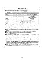
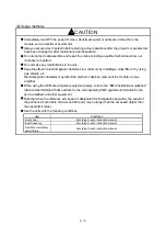
Store and use the unit in the following environmental conditions.
Environment
Conditions
Module/Servo amplifier
Servomotor
Ambient
temperature
According to each instruction manual.
0°C to +40°C (With no freezing)
(32°F to +104°F)
Ambient humidity
According to each instruction manual.
80% RH or less
(With no dew condensation)
Storage
temperature
According to each instruction manual.
-20°C to +65°C
(-4°F to +149°F)
Atmosphere
Indoors (where not subject to direct sunlight).
No corrosive gases, flammable gases, oil mist or dust must exist
Altitude
According to each instruction manual
Vibration
According to each instruction manual
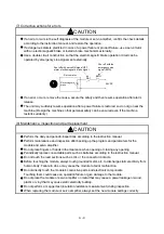
When coupling with the servomotor shaft end, do not apply impact such as by hitting with a
hammer. Doing so may lead to detector damage.
Do not apply a load larger than the tolerable load onto the servomotor shaft. Doing so may lead
to shaft breakage.
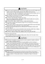
When not using the module for a long time, disconnect the power line from the module or servo
amplifier.
Place the module and servo amplifier in static electricity preventing vinyl bags and store.
When storing for a long time, please contact with our sales representative.
Also, execute a trial operation.
Make sure that the connectors for the servo amplifier and peripheral devices have been securely
installed until a click is heard.
Not doing so could lead to a poor connection, resulting in erroneous input and output.
When fumigants that contain halogen materials such as fluorine, chlorine, bromine, and iodine are
used for disinfecting and protecting wooden packaging from insects, they cause malfunction when
entering our products.
Please take necessary precautions to ensure that remaining materials from fumigant do not enter
our products, or treat packaging with methods other than fumigation (heat method). Additionally,
disinfect and protect wood from insects before packing products.
The module and the servo amplifier must not be used with parts which contain halogen-series
flame retardant materials (such as bromine) under coexisting conditions.
Summary of Contents for MELSEC-L Series
Page 2: ......
Page 30: ...MEMO ...
Page 70: ...2 10 Chapter 2 System Configuration MEMO ...
Page 83: ...3 13 Chapter 3 Specifications and Functions MEMO ...
Page 103: ...3 33 Chapter 3 Specifications and Functions MEMO ...
Page 107: ...3 37 Chapter 3 Specifications and Functions MEMO ...
Page 111: ...3 41 Chapter 3 Specifications and Functions MEMO ...
Page 115: ...3 45 Chapter 3 Specifications and Functions MEMO ...
Page 140: ...4 22 Chapter 4 Installation Wiring and Maintenance of the Product MEMO ...
Page 253: ...5 113 Chapter 5 Data Used for Positioning Control MEMO ...
Page 342: ...5 202 Chapter 5 Data Used for Positioning Control MEMO ...
Page 438: ...7 20 Chapter 7 Memory Configuration and Data Process MEMO ...
Page 440: ...MEMO ...
Page 485: ...9 25 Chapter 9 Major Positioning Control MEMO ...
Page 594: ...9 134 Chapter 9 Major Positioning Control MEMO ...
Page 624: ...10 30 Chapter 10 High Level Positioning Control MEMO ...
Page 656: ...11 32 Chapter 11 Manual Control MEMO ...
Page 690: ...12 34 Chapter 12 Expansion Control MEMO ...
Page 798: ...13 108 Chapter 13 Control Sub Functions MEMO ...
Page 866: ...14 68 Chapter 14 Common Functions MEMO ...
Page 884: ...15 18 Chapter 15 Dedicated Instructions MEMO ...
Page 899: ...16 15 Chapter 16 Troubleshooting MEMO ...
Page 1036: ...Appendix 88 Appendices MEMO ...
Page 1039: ......


