


11 - 27
Chapter 11 Manual Control
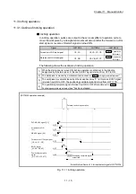
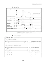
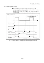
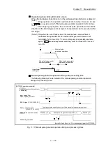
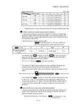
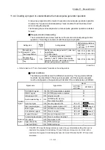
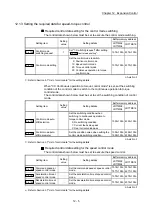
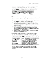
Normal timing times
Unit : [ms]
Operation
cycle
t1 t2 t3 t4
LD77MS2
0.88
0.9
7.0 to 14.0
18.0 to 25.0
9.6
1.77
1.8
7.0 to 14.0
18.0 to 25.0
9.6
LD77MS4
0.88
0.9
7.0 to 14.0
18.0 to 25.0
9.6
1.77
1.8
7.0 to 14.0
18.0 to 25.0
9.6
LD77MS16
0.88
0.9
7.0 to 14.0
18.0 to 25.0
9.6
1.77
1.8
7.0 to 14.0
18.0 to 25.0
9.6
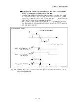
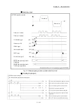
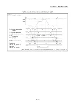
Delays may occur in the t1 timing time due to the operation status of other axes.
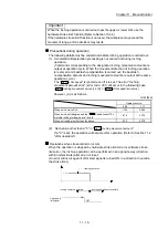
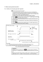
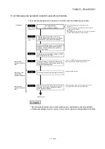
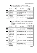
Position control by manual pulse generator operation
In manual pulse generator operation, the position is moved by a "manual pulse
generator 1 pulse movement amount" per pulse. The current feed value in the
positioning control by manual pulse generator operation can be calculated using
the expression shown below.
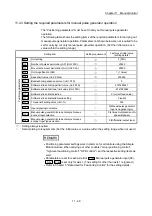
Current feed value = Number of input pulses
×
Cd.20
Manual pulse generator 1 pulse input magnification
× Manual pulse generator 1 pulse movement amount
Pr.1
Unit setting
mm inch
degree
PLS
Manual pulse generator
1 pulse movement
amount
0.1µm 0.00001inch
0.00001degree 1PLS
For example, when "
Pr.1
Unit setting
" is mm and "
Cd.20
Manual pulse generator 1
pulse input magnification
" is 2, and 100 pulses are input from the manual pulse
generator, the current feed value is as follows.
100 × 2 × 0.1 = 20 [µm] ("
Md.20
Current feed value
"=200)
The number of pulses output actually to the servo amplifier is "Manual pulse
generator 1pulse movement amount/movement amount per pulse".
The movement amount per pulse can be calculated using the expression shown
below.
Movement amount per pulse =
Pr.3 Movement amount per rotation(AL)
Pr.2 Number of pulses per rotation(AP)
Pr.4
Unit magnification(AM)
For example, when "
Pr.1
Unit setting
" is mm and the movement amount per pulse
is 1
μ
m, 0.1/1 = 1/10, i.e., the output to the servo amplifier per pulse from the
manual pulse generator is 1/10pulse. Thus, the Simple Motion module outputs
1pulse to the servo amplifier after receiving 10pulses from the manual pulse
generator.
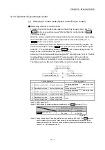
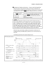
Speed control by manual pulse generation operation
The speed during positioning control by manual pulse generator operation is a
speed corresponding to the number of input pulses per unit time, and can be
obtained using the following equation.
Output command frequency = Input frequency
Cd.20
Manual pulse generator 1 pulse
input magnification
Summary of Contents for MELSEC-L Series
Page 2: ......
Page 30: ...MEMO ...
Page 70: ...2 10 Chapter 2 System Configuration MEMO ...
Page 83: ...3 13 Chapter 3 Specifications and Functions MEMO ...
Page 103: ...3 33 Chapter 3 Specifications and Functions MEMO ...
Page 107: ...3 37 Chapter 3 Specifications and Functions MEMO ...
Page 111: ...3 41 Chapter 3 Specifications and Functions MEMO ...
Page 115: ...3 45 Chapter 3 Specifications and Functions MEMO ...
Page 140: ...4 22 Chapter 4 Installation Wiring and Maintenance of the Product MEMO ...
Page 253: ...5 113 Chapter 5 Data Used for Positioning Control MEMO ...
Page 342: ...5 202 Chapter 5 Data Used for Positioning Control MEMO ...
Page 438: ...7 20 Chapter 7 Memory Configuration and Data Process MEMO ...
Page 440: ...MEMO ...
Page 485: ...9 25 Chapter 9 Major Positioning Control MEMO ...
Page 594: ...9 134 Chapter 9 Major Positioning Control MEMO ...
Page 624: ...10 30 Chapter 10 High Level Positioning Control MEMO ...
Page 656: ...11 32 Chapter 11 Manual Control MEMO ...
Page 690: ...12 34 Chapter 12 Expansion Control MEMO ...
Page 798: ...13 108 Chapter 13 Control Sub Functions MEMO ...
Page 866: ...14 68 Chapter 14 Common Functions MEMO ...
Page 884: ...15 18 Chapter 15 Dedicated Instructions MEMO ...
Page 899: ...16 15 Chapter 16 Troubleshooting MEMO ...
Page 1036: ...Appendix 88 Appendices MEMO ...
Page 1039: ......


