


11 - 25
Chapter 11 Manual Control
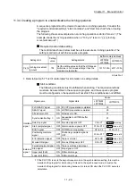
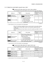
Restricted items
A pulse generator such as a manual pulse generator is required to carry out
manual pulse generator operation.
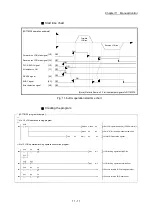
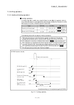
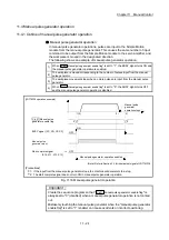
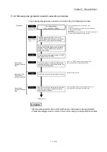
Precautions during operation
The following details must be understood before carrying out manual pulse
generator operation.
(1) The speed during manual pulse generator operation is not limited by the "
Pr.8
Speed limit value
".
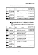
(2) If "
Cd.21
Manual pulse generator enable flag
" is turned ON while the Simple
Motion module is BUSY (BUSY signal ON), the warning "Start during
operation" (warning code: 100)
will occur.
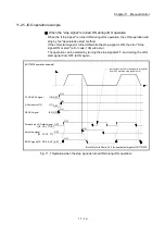
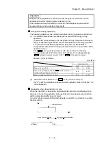
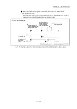
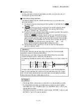
(3) If a stop factor occurs during manual pulse generator operation, the operation
will stop, and the BUSY signal will turn OFF.
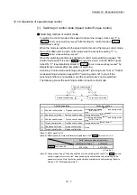
At this time, "
Cd.21
Manual pulse generator enable flag
" remain ON. However,
manual pulse generator operation will not be possible. To carry out manual
pulse generator operation again, measures must be carried out to eliminate
the stop factor. Once eliminated, the operation can be carried out again by
turning "
Cd.21
Manual pulse generator enable flag
" ON
OFF ON.
(Note that this excludes hardware/software stroke limit error.)
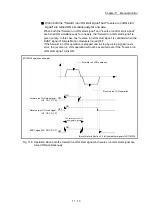
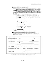
(4) Command will not be output if an error occurs when the manual pulse
generator operation starts.
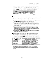
Important
The speed command is issued according to the input from the manual pulse
generator irrelevant of the speed limit setting.
When the speed command is larger than 62914560 [PLS/s], the servo alarm
"Command frequency error" (alarm No.: 35) will occur.
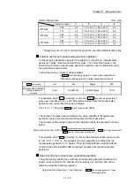
The following calculation formula is used to judge whether or not a servo alarm will
occur.
(Speed command) =
Manual pulse
generator 1
pulse input
magnification
Manual pulse
generator 1
pulse movement
amount
Number of pulses per rotation
Movement amount per rotation
Number of
input pulses
for one
second
If a large value is set to the manual pulse generator 1 pulse input magnification,
there is a high possibility of the servo alarm "Command frequency error" (alarm
No.: 35) occurrence. Note that the servomotor does not work rapidly by sudden
pulse input even if the servo alarm does not occur.
REMARK
One Simple Motion module can be connected to one manual pulse generator.
The Simple Motion module can simultaneously command to servo amplifier
(LD77MS2: Axis 1 to 2, LD77MS4: Axis 1 to 4, LD77MS16: Axis 1 to 16) by one
manual pulse generator.
(Simultaneous operation (LD77MS2: 1 axis to 2 axes, LD77MS4: 1 axis to 4 axes,
LD77MS16: 1 axis to 16 axes) is possible.)
Summary of Contents for MELSEC-L Series
Page 2: ......
Page 30: ...MEMO ...
Page 70: ...2 10 Chapter 2 System Configuration MEMO ...
Page 83: ...3 13 Chapter 3 Specifications and Functions MEMO ...
Page 103: ...3 33 Chapter 3 Specifications and Functions MEMO ...
Page 107: ...3 37 Chapter 3 Specifications and Functions MEMO ...
Page 111: ...3 41 Chapter 3 Specifications and Functions MEMO ...
Page 115: ...3 45 Chapter 3 Specifications and Functions MEMO ...
Page 140: ...4 22 Chapter 4 Installation Wiring and Maintenance of the Product MEMO ...
Page 253: ...5 113 Chapter 5 Data Used for Positioning Control MEMO ...
Page 342: ...5 202 Chapter 5 Data Used for Positioning Control MEMO ...
Page 438: ...7 20 Chapter 7 Memory Configuration and Data Process MEMO ...
Page 440: ...MEMO ...
Page 485: ...9 25 Chapter 9 Major Positioning Control MEMO ...
Page 594: ...9 134 Chapter 9 Major Positioning Control MEMO ...
Page 624: ...10 30 Chapter 10 High Level Positioning Control MEMO ...
Page 656: ...11 32 Chapter 11 Manual Control MEMO ...
Page 690: ...12 34 Chapter 12 Expansion Control MEMO ...
Page 798: ...13 108 Chapter 13 Control Sub Functions MEMO ...
Page 866: ...14 68 Chapter 14 Common Functions MEMO ...
Page 884: ...15 18 Chapter 15 Dedicated Instructions MEMO ...
Page 899: ...16 15 Chapter 16 Troubleshooting MEMO ...
Page 1036: ...Appendix 88 Appendices MEMO ...
Page 1039: ......


