

12 - 23
Chapter 12 Expansion Control
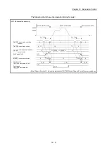
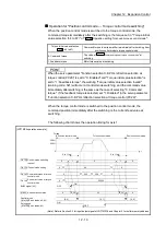
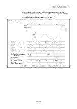
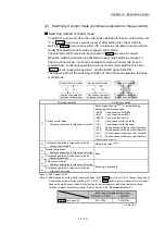
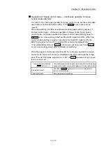
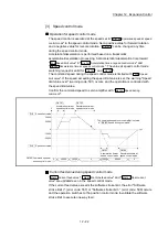
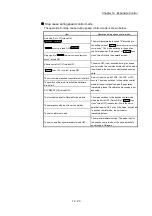
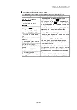
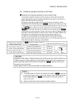
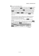
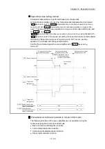
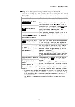
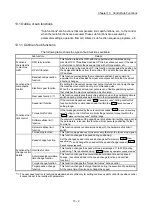
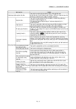
Stop cause during speed control mode
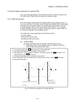
The operation for stop cause during speed control mode is shown below.
Item
Operation during speed control mode
Axis stop [Y4 to Y7] turned ON.
LD77MS2
LD77MS4
The motor decelerates to speed "0" according to
the setting value of "
Cd.142
Deceleration time at speed
control mode
". The mode switches to the position
control mode when "Zero speed" of "
Md.108
Servo
status
" turns ON, and the operation stops.
"
Cd.180
Axis stop"
turned ON.
LD77MS16
Stop signal of "
Cd.44
External input signal operation
device
" turned ON.
All axis servo ON [Y1] turned OFF.
The servo OFF is not executed during the speed
control mode. The command status when the mode
is switched to the position control mode becomes
valid.
"
Cd.100
Servo OFF command
" turned ON.
The current value reached the software stroke limit. An error (error code: 507, 508, 104, 105, or 101)
occurs. The mode switches to the position control
mode at the current position, and the operation
immediately stops. (Deceleration processing is not
executed.)
The position of the motor reached the hardware
stroke limit.
PLC READY [Y0] turned OFF.
The forced stop input to Simple Motion module.
The mode switches to the position control mode
when the servo OFF (Servo ON of "
Md.108
Servo
status
" turns OFF) is executed. (While the servo
amplifier is servo OFF, even if the mode is switched
to position control mode, the servomotor
immediately stops.
The emergency stop input to servo amplifier.
The servo alarm occurred.
The servo amplifier's power supply turned OFF.
The motor immediately stops. (The mode is set to
the position control mode at the servo amplifier's
power supply ON again.)
Summary of Contents for MELSEC-L Series
Page 2: ......
Page 30: ...MEMO ...
Page 70: ...2 10 Chapter 2 System Configuration MEMO ...
Page 83: ...3 13 Chapter 3 Specifications and Functions MEMO ...
Page 103: ...3 33 Chapter 3 Specifications and Functions MEMO ...
Page 107: ...3 37 Chapter 3 Specifications and Functions MEMO ...
Page 111: ...3 41 Chapter 3 Specifications and Functions MEMO ...
Page 115: ...3 45 Chapter 3 Specifications and Functions MEMO ...
Page 140: ...4 22 Chapter 4 Installation Wiring and Maintenance of the Product MEMO ...
Page 253: ...5 113 Chapter 5 Data Used for Positioning Control MEMO ...
Page 342: ...5 202 Chapter 5 Data Used for Positioning Control MEMO ...
Page 438: ...7 20 Chapter 7 Memory Configuration and Data Process MEMO ...
Page 440: ...MEMO ...
Page 485: ...9 25 Chapter 9 Major Positioning Control MEMO ...
Page 594: ...9 134 Chapter 9 Major Positioning Control MEMO ...
Page 624: ...10 30 Chapter 10 High Level Positioning Control MEMO ...
Page 656: ...11 32 Chapter 11 Manual Control MEMO ...
Page 690: ...12 34 Chapter 12 Expansion Control MEMO ...
Page 798: ...13 108 Chapter 13 Control Sub Functions MEMO ...
Page 866: ...14 68 Chapter 14 Common Functions MEMO ...
Page 884: ...15 18 Chapter 15 Dedicated Instructions MEMO ...
Page 899: ...16 15 Chapter 16 Troubleshooting MEMO ...
Page 1036: ...Appendix 88 Appendices MEMO ...
Page 1039: ......


