


9 - 19
Chapter 9 Major Positioning Control
POINT
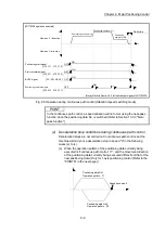
(1) When the upper/lower limit value of the axis which set the software stroke limit
as valid are changed, perform the machine OPR after that.
(2) When the software stroke limit is set as valid in the incremental data system,
perform the machine OPR after power supply on.
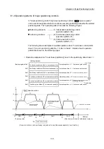
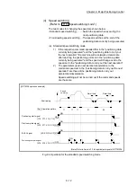
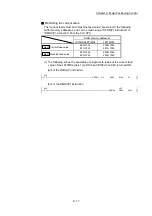
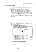
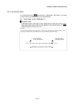
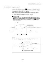
[3] Positioning control method when the control unit is set to "degree"
1) Absolute system
(a) When the software stroke limit is invalid
Positioning is carried out in the nearest direction to the designated
address, using the current value as a reference.
(This is called "shortcut control".)
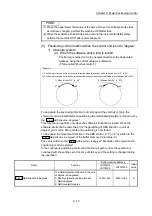
Example
1) Positioning is carried out in a clockwise direction when the current value is moved from 315° to 45°.
2) Positioning is carried out in a counterclockwise direction when the current value is moved from 45° to 315°.
315°
45°
315°
45°
1) Moved from 315° to 45°
2) Moved from 45° to 315°
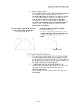
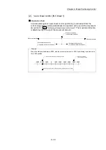
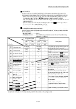
To designate the positioning direction (not carrying out the shortcut control), the
shortcut control is invalidated and positioning in a designated direction is carried out by
the "
Cd.40
ABS direction in degrees
".
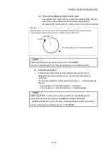
This function can perform only when the software stroke limit is invalid. When the
software stroke limit is valid, the error "Illegal setting of ABS direction in unit of
degree" (error code: 546) occurs and positioning is not started.
To designate the movement direction in the ABS control, a "1" or "2" is written to the
"
Cd.40
ABS direction in degrees
" of the buffer memory (initial value: 0).
The value written to the "
Cd.40
ABS direction in degrees
" becomes valid only when the
positioning control is started.
In the continuous positioning control and continuous path control, the operation is
continued with the setting set at the time of start even if the setting is changed during
the operation.
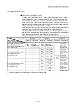
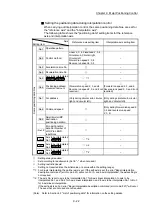
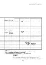
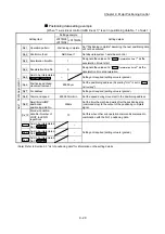
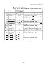
Name Function
Buffer memory address
Initial
value
LD77MS2
LD77MS4
LD77MS16
Cd.40
ABS direction in degrees
The ABS movement direction in the unit
of degree is designated.
0: Shortcut (direction setting invalid)
1: ABS clockwise
2: ABS counterclockwise
1550+100n 4350+100n 0
Summary of Contents for MELSEC-L Series
Page 2: ......
Page 30: ...MEMO ...
Page 70: ...2 10 Chapter 2 System Configuration MEMO ...
Page 83: ...3 13 Chapter 3 Specifications and Functions MEMO ...
Page 103: ...3 33 Chapter 3 Specifications and Functions MEMO ...
Page 107: ...3 37 Chapter 3 Specifications and Functions MEMO ...
Page 111: ...3 41 Chapter 3 Specifications and Functions MEMO ...
Page 115: ...3 45 Chapter 3 Specifications and Functions MEMO ...
Page 140: ...4 22 Chapter 4 Installation Wiring and Maintenance of the Product MEMO ...
Page 253: ...5 113 Chapter 5 Data Used for Positioning Control MEMO ...
Page 342: ...5 202 Chapter 5 Data Used for Positioning Control MEMO ...
Page 438: ...7 20 Chapter 7 Memory Configuration and Data Process MEMO ...
Page 440: ...MEMO ...
Page 485: ...9 25 Chapter 9 Major Positioning Control MEMO ...
Page 594: ...9 134 Chapter 9 Major Positioning Control MEMO ...
Page 624: ...10 30 Chapter 10 High Level Positioning Control MEMO ...
Page 656: ...11 32 Chapter 11 Manual Control MEMO ...
Page 690: ...12 34 Chapter 12 Expansion Control MEMO ...
Page 798: ...13 108 Chapter 13 Control Sub Functions MEMO ...
Page 866: ...14 68 Chapter 14 Common Functions MEMO ...
Page 884: ...15 18 Chapter 15 Dedicated Instructions MEMO ...
Page 899: ...16 15 Chapter 16 Troubleshooting MEMO ...
Page 1036: ...Appendix 88 Appendices MEMO ...
Page 1039: ......


