

6 - 65
Chapter 6 Sequence Program Used for Positioning Control
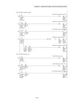
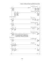
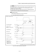
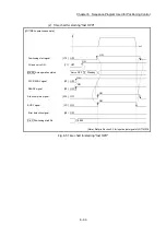
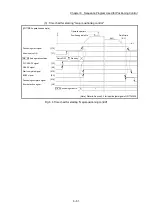
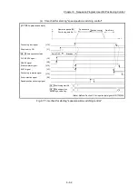
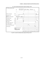
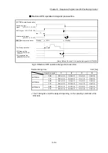
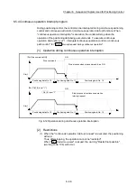
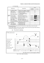
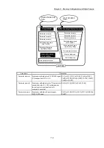
Position control operation timing and process time
[LD77MS4 operation example]
t1
t2
t3
t4
t5
t2
t6
Cd. 7 M code OFF request
Standby
Position control
Standby
BUSY signal
Positioning operation
Md. 26 Axis operation status
Cd. 7 M code OFF request
Positioning start signal
[Y10, Y11, Y12, Y13]
[XC, XD, XE, XF]
M code ON signal
(WITH mode) [X4, X5, X6, X7]
Start complete signal
[X10, X11, X12, X13]
M code ON signal
(AFTER mode)
[X4, X5, X6, X7]
[X14, X15, X16, X17]
Positioning complete signal
OPR complete flag
( Md. 31 Status: b4)
(Note): Refer to Section 3.3 for input/output signal of LD77MS16.
Fig. 6.10 Position control operation timing and process time
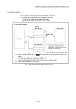
When the positioning start signal turns ON, if the "positioning complete signal" or
"OPR complete flag" are already ON, the "positioning complete signal" or "OPR
complete flag" will turn OFF when the positioning start signal turns ON.
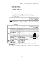
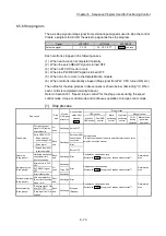
Normal timing time
Unit: [ms]
Operation
cycle
t1 t2 t3 t4 t5
t6
LD77MS2
0.88
0.2 to 0.3 0 to 0.9
0 to 0.9 2.0 to 2.7 0 to 0.9 Follows parameters
1.77
0.2 to 0.3 0 to 1.8
0 to 1.8 2.6 to 3.9 0 to 1.8 Follows parameters
LD77MS4
0.88
0.2 to 0.3 0 to 0.9
0 to 0.9 1.9 to 2.7 0 to 0.9 Follows parameters
1.77
0.2 to 0.3 0 to 1.8
0 to 1.8 2.6 to 3.9 0 to 1.8 Follows parameters
LD77MS16
0.88
0.3 to 1.4 0 to 0.9
0 to 0.9 2.5 to 3.4 0 to 0.9 Follows parameters
1.77
0.3 to 1.4 0 to 1.8
0 to 1.8 3.4 to 5.2 0 to 1.8 Follows parameters
The t1 timing time could be delayed depending on the operating conditions of
the other axis.
Summary of Contents for MELSEC-L Series
Page 2: ......
Page 30: ...MEMO ...
Page 70: ...2 10 Chapter 2 System Configuration MEMO ...
Page 83: ...3 13 Chapter 3 Specifications and Functions MEMO ...
Page 103: ...3 33 Chapter 3 Specifications and Functions MEMO ...
Page 107: ...3 37 Chapter 3 Specifications and Functions MEMO ...
Page 111: ...3 41 Chapter 3 Specifications and Functions MEMO ...
Page 115: ...3 45 Chapter 3 Specifications and Functions MEMO ...
Page 140: ...4 22 Chapter 4 Installation Wiring and Maintenance of the Product MEMO ...
Page 253: ...5 113 Chapter 5 Data Used for Positioning Control MEMO ...
Page 342: ...5 202 Chapter 5 Data Used for Positioning Control MEMO ...
Page 438: ...7 20 Chapter 7 Memory Configuration and Data Process MEMO ...
Page 440: ...MEMO ...
Page 485: ...9 25 Chapter 9 Major Positioning Control MEMO ...
Page 594: ...9 134 Chapter 9 Major Positioning Control MEMO ...
Page 624: ...10 30 Chapter 10 High Level Positioning Control MEMO ...
Page 656: ...11 32 Chapter 11 Manual Control MEMO ...
Page 690: ...12 34 Chapter 12 Expansion Control MEMO ...
Page 798: ...13 108 Chapter 13 Control Sub Functions MEMO ...
Page 866: ...14 68 Chapter 14 Common Functions MEMO ...
Page 884: ...15 18 Chapter 15 Dedicated Instructions MEMO ...
Page 899: ...16 15 Chapter 16 Troubleshooting MEMO ...
Page 1036: ...Appendix 88 Appendices MEMO ...
Page 1039: ......


