


5 - 27
Chapter 5 Data Used for Positioning Control
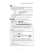
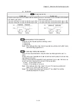
POINT
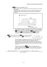
For the 2-axis or more interpolation control, the bias speed at start is applied by the
setting of "
Pr.20
Interpolation speed designation method
".
"0: Composite speed"
: Bias speed at start set to the reference axis is applied
to the composite command speed.
"1: Reference axis speed": Bias speed at start is applied to the reference axis.
(1) Precautionary notes
(a) "
Pr.7
Bias speed at start
" is valid regardless of motor type. Set "0" when
using the motor other than the stepping motor. Otherwise, it may cause
vibration or impact even though an error does not occur.
(b) Set "
Pr.7
Bias speed at start
" according to the specification of stepping
motor driver. If the setting is outside the range, it may cause the following
troubles by rapid speed change or overload.
Stepping motor steps out.
An error occurs in the stepping motor driver.
(c) In synchronous control, when "
Pr.7
Bias speed at start
" is set to the servo
input axis, the bias speed at start is applied to the servo input axis. Note
that the unexpected operation might be generated to the output axis.
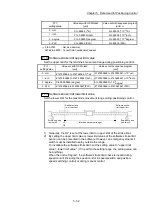
(d) Set "
Pr.7
Bias speed at start
" within the following range.
"
Pr.8
Speed limit value
" >= "
Pr.46
OPR speed
" >= "
Pr.47
Creep speed
" >= "
Pr.7
Bias speed at start
"
(e) If following data are less than "
Pr.7
Bias speed at start
", the warning
"Below bias speed" (warning code: 114) will occur, and it will operate at
"
Pr.7
Bias speed at start
".
"
Da.8
Command speed
" of positioning data
"
Da.8
Command speed
" of next point for continuous path control
"
Cd.14
New speed value
" for speed change function
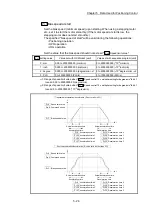
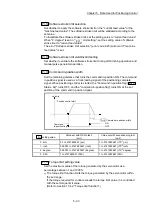
(f) When using S-curve acceleration/deceleration processing and bias speed
at start together, S-curve acceleration/deceleration processing is carried
out based on the acceleration/deceleration time set by user, "
Pr.8
Speed
limit value
" and "
Pr.35
S-curve ratio
" (1 to 100%) in the section of
acceleration/deceleration from bias speed at start to command speed.
Summary of Contents for MELSEC-L Series
Page 2: ......
Page 30: ...MEMO ...
Page 70: ...2 10 Chapter 2 System Configuration MEMO ...
Page 83: ...3 13 Chapter 3 Specifications and Functions MEMO ...
Page 103: ...3 33 Chapter 3 Specifications and Functions MEMO ...
Page 107: ...3 37 Chapter 3 Specifications and Functions MEMO ...
Page 111: ...3 41 Chapter 3 Specifications and Functions MEMO ...
Page 115: ...3 45 Chapter 3 Specifications and Functions MEMO ...
Page 140: ...4 22 Chapter 4 Installation Wiring and Maintenance of the Product MEMO ...
Page 253: ...5 113 Chapter 5 Data Used for Positioning Control MEMO ...
Page 342: ...5 202 Chapter 5 Data Used for Positioning Control MEMO ...
Page 438: ...7 20 Chapter 7 Memory Configuration and Data Process MEMO ...
Page 440: ...MEMO ...
Page 485: ...9 25 Chapter 9 Major Positioning Control MEMO ...
Page 594: ...9 134 Chapter 9 Major Positioning Control MEMO ...
Page 624: ...10 30 Chapter 10 High Level Positioning Control MEMO ...
Page 656: ...11 32 Chapter 11 Manual Control MEMO ...
Page 690: ...12 34 Chapter 12 Expansion Control MEMO ...
Page 798: ...13 108 Chapter 13 Control Sub Functions MEMO ...
Page 866: ...14 68 Chapter 14 Common Functions MEMO ...
Page 884: ...15 18 Chapter 15 Dedicated Instructions MEMO ...
Page 899: ...16 15 Chapter 16 Troubleshooting MEMO ...
Page 1036: ...Appendix 88 Appendices MEMO ...
Page 1039: ......


