


9 - 15
Chapter 9 Major Positioning Control
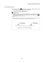
9.1.3 Designating the positioning address
The following shows the two methods for commanding the position in control using
positioning data.
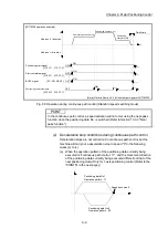
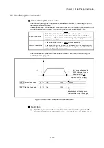
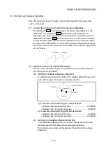
Absolute system
Positioning is carried out to a designated position (absolute address) having the
OP as a reference. This address is regarded as the positioning address. (The start
point can be anywhere.)
Address
100
Address
150
Address
300
100
A point
150
B point
300
C point
Within the stroke limit range
Address 150
Address
100
Address 100
Address 150
Start point
End point
OP
(Reference point)
Fig. 9.6 Absolute system positioning
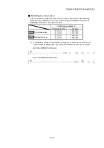
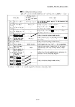
Incremental system
The position where the machine is currently stopped is regarded as the start point,
and positioning is carried out for a designated movement amount in a designated
movement direction.
Movement amount
+100
Movement
amount -150
Movement amount
-100
100
150
300
Movement amount-100
A point
B point
Within the stroke limit range
C point
Movement amount
+100
Start point
End point
250
OP
(Reference point)
Fig. 9.7 Incremental system positioning
Summary of Contents for MELSEC-L Series
Page 2: ......
Page 30: ...MEMO ...
Page 70: ...2 10 Chapter 2 System Configuration MEMO ...
Page 83: ...3 13 Chapter 3 Specifications and Functions MEMO ...
Page 103: ...3 33 Chapter 3 Specifications and Functions MEMO ...
Page 107: ...3 37 Chapter 3 Specifications and Functions MEMO ...
Page 111: ...3 41 Chapter 3 Specifications and Functions MEMO ...
Page 115: ...3 45 Chapter 3 Specifications and Functions MEMO ...
Page 140: ...4 22 Chapter 4 Installation Wiring and Maintenance of the Product MEMO ...
Page 253: ...5 113 Chapter 5 Data Used for Positioning Control MEMO ...
Page 342: ...5 202 Chapter 5 Data Used for Positioning Control MEMO ...
Page 438: ...7 20 Chapter 7 Memory Configuration and Data Process MEMO ...
Page 440: ...MEMO ...
Page 485: ...9 25 Chapter 9 Major Positioning Control MEMO ...
Page 594: ...9 134 Chapter 9 Major Positioning Control MEMO ...
Page 624: ...10 30 Chapter 10 High Level Positioning Control MEMO ...
Page 656: ...11 32 Chapter 11 Manual Control MEMO ...
Page 690: ...12 34 Chapter 12 Expansion Control MEMO ...
Page 798: ...13 108 Chapter 13 Control Sub Functions MEMO ...
Page 866: ...14 68 Chapter 14 Common Functions MEMO ...
Page 884: ...15 18 Chapter 15 Dedicated Instructions MEMO ...
Page 899: ...16 15 Chapter 16 Troubleshooting MEMO ...
Page 1036: ...Appendix 88 Appendices MEMO ...
Page 1039: ......


