


14 - 28
Chapter 14 Common Functions
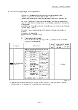
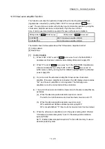
14.8 Virtual servo amplifier function
This function executes the operation virtually without connecting servo amplifiers
(regarded as connected) by setting "4097, 4128" in servo parameter "
Pr.100
Servo
series
". The synchronous control with virtually input command is possible by using the
virtual servo amplifier axis as servo input axis of synchronous control.
Also, it can be used as simulation operation for axes without servo amplifiers.
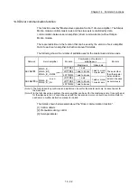
Setting value of "
Pr.97
SSCNET setting
"
Setting value of "
Pr.100
Servo series
"
0: SSCNET
4097: Virtual servo amplifier (MR-J3)
1: SSCNET /H
4128: Virtual servo amplifier (MR-J4)
The details shown below explain about the "Virtual servo amplifier function".
[1] Control details
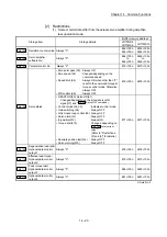
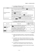
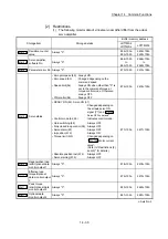
[2] Restrictions
[1] Control details
(1) When "4097, 4128" is set in "
Pr.100
Servo series
" set in the flash ROM, it
operates as virtual servo amplifier immediately after power supply ON.
(2) When "0" is set in "
Pr.100
Servo series
" set in the flash ROM, it operates as
virtual servo amplifier by setting "4097, 4128" in "
Pr.100
Servo series
" of
buffer memory and by turning the PLC READY signal [Y0] OFF to ON after
power supply ON.
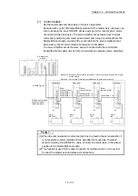
(3) Do not connect the actual servo amplifier to axis set as virtual servo
amplifier. If the servo amplifier is connected, the LED display status remains
"Ab." and the servo amplifier is not recognized. The following servo
amplifiers cannot be connected until the end station.
(4) The current feed value and machine feed value of virtual servo amplifier are
as follows.
(a) When the absolute position detection system is invalid
The both of current feed value and machine feed value are set to "0".
(b) When the absolute position detection system is valid
OP is established: Address at latest power supply OFF
OP is not established: "0" (Feed current value and machine feed value)
(5) When the virtual servo amplifier is set in the system setting of GX Works2,
"0: Disabled (incremental system)" is set in "Absolute position detection
system (PA03)".
Set "1: Enabled (absolute position system)" to the buffer memory to use as
absolute position system.
Summary of Contents for MELSEC-L Series
Page 2: ......
Page 30: ...MEMO ...
Page 70: ...2 10 Chapter 2 System Configuration MEMO ...
Page 83: ...3 13 Chapter 3 Specifications and Functions MEMO ...
Page 103: ...3 33 Chapter 3 Specifications and Functions MEMO ...
Page 107: ...3 37 Chapter 3 Specifications and Functions MEMO ...
Page 111: ...3 41 Chapter 3 Specifications and Functions MEMO ...
Page 115: ...3 45 Chapter 3 Specifications and Functions MEMO ...
Page 140: ...4 22 Chapter 4 Installation Wiring and Maintenance of the Product MEMO ...
Page 253: ...5 113 Chapter 5 Data Used for Positioning Control MEMO ...
Page 342: ...5 202 Chapter 5 Data Used for Positioning Control MEMO ...
Page 438: ...7 20 Chapter 7 Memory Configuration and Data Process MEMO ...
Page 440: ...MEMO ...
Page 485: ...9 25 Chapter 9 Major Positioning Control MEMO ...
Page 594: ...9 134 Chapter 9 Major Positioning Control MEMO ...
Page 624: ...10 30 Chapter 10 High Level Positioning Control MEMO ...
Page 656: ...11 32 Chapter 11 Manual Control MEMO ...
Page 690: ...12 34 Chapter 12 Expansion Control MEMO ...
Page 798: ...13 108 Chapter 13 Control Sub Functions MEMO ...
Page 866: ...14 68 Chapter 14 Common Functions MEMO ...
Page 884: ...15 18 Chapter 15 Dedicated Instructions MEMO ...
Page 899: ...16 15 Chapter 16 Troubleshooting MEMO ...
Page 1036: ...Appendix 88 Appendices MEMO ...
Page 1039: ......


