

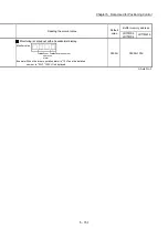

5 - 149
Chapter 5 Data Used for Positioning Control
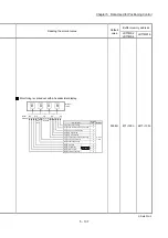
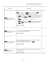
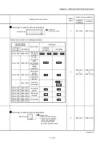
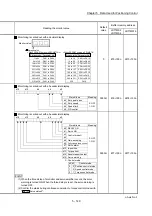
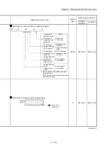
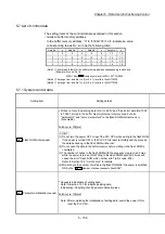
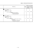
Reading the monitor value
Default
value
Buffer memory address
LD77MS2
LD77MS4
LD77MS16
Monitoring is carried out with a decimal display.
Monitor value
Storage value
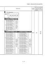
When SSCNET setting is SSCNET /H
When SSCNET setting is SSCNET
Storage value Parameter No.
1 to 64
PA01 to PA64
64 to 128
PB01 to PB64
129 to 192
PC01 to PC64
193 to 256
PD01 to PD64
257 to 320
PE01 to PE64
321 to 384
PF01 to PF64
385 to 448
Po01 to Po64
449 to 512
PS01 to PS64
513 to 576
PL01 to PL64
Storage value Parameter No.
1 to 18
PA01 to PA18
19 to 63
PB01 to PB45
64 to 95
PC01 to PC32
96 to 127
PD01 to PD32
128 to 167
PE01 to PE40
168 to 183
PF01 to PF16
184 to 199
Po01 to Po16
200 to 231
PS01 to PS32
232
PA19
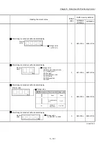
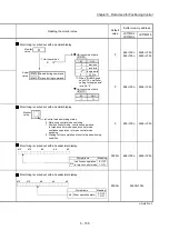
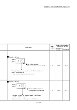
0 870+100n
2470+100n
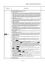
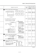
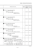
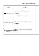
Monitoring is carried out with a hexadecimal display.
b15
b12
b8
b4
b0
b0
b3
0: OFF
1: ON
Zero point pass
Zero speed
Stored items
Meaning
b4 Speed limit
b8 PID control
0000H
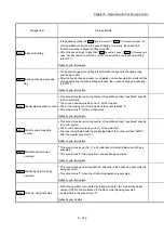
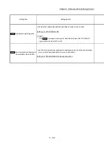
876+100n 2476+100n
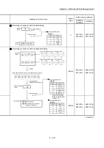
Monitoring is carried out with a hexadecimal display.
b15
b12
b8
b4
b0
b0
b1
0: OFF
1: ON
Stored items
Meaning
READY ON
Servo ON
b3
b2
Control mode
b7
b12
b13
b14
In-position
Torque limit
Servo alarm
Servo warning
Absolute position lost
b15
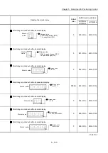
b3
b2
0
0
0
1
1
0
Control mode
Position control mode
Speed control mode
Torque control mode
: Control mode
b4
b5
Gain switching
Fully closed loop control
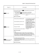
POINT
(1) When the forced stop of controller and servo amplifier occurs, the servo
warning is turned ON. When the forced stop is reset, the servo warning is
turned OFF.
(2) Confirm the status during continuous operation to torque control mode with
"
Md.125
Servo status3
".
0000H
877+100n 2477+100n
n: Axis No.-1
Summary of Contents for MELSEC-L Series
Page 2: ......
Page 30: ...MEMO ...
Page 70: ...2 10 Chapter 2 System Configuration MEMO ...
Page 83: ...3 13 Chapter 3 Specifications and Functions MEMO ...
Page 103: ...3 33 Chapter 3 Specifications and Functions MEMO ...
Page 107: ...3 37 Chapter 3 Specifications and Functions MEMO ...
Page 111: ...3 41 Chapter 3 Specifications and Functions MEMO ...
Page 115: ...3 45 Chapter 3 Specifications and Functions MEMO ...
Page 140: ...4 22 Chapter 4 Installation Wiring and Maintenance of the Product MEMO ...
Page 253: ...5 113 Chapter 5 Data Used for Positioning Control MEMO ...
Page 342: ...5 202 Chapter 5 Data Used for Positioning Control MEMO ...
Page 438: ...7 20 Chapter 7 Memory Configuration and Data Process MEMO ...
Page 440: ...MEMO ...
Page 485: ...9 25 Chapter 9 Major Positioning Control MEMO ...
Page 594: ...9 134 Chapter 9 Major Positioning Control MEMO ...
Page 624: ...10 30 Chapter 10 High Level Positioning Control MEMO ...
Page 656: ...11 32 Chapter 11 Manual Control MEMO ...
Page 690: ...12 34 Chapter 12 Expansion Control MEMO ...
Page 798: ...13 108 Chapter 13 Control Sub Functions MEMO ...
Page 866: ...14 68 Chapter 14 Common Functions MEMO ...
Page 884: ...15 18 Chapter 15 Dedicated Instructions MEMO ...
Page 899: ...16 15 Chapter 16 Troubleshooting MEMO ...
Page 1036: ...Appendix 88 Appendices MEMO ...
Page 1039: ......


