


9 - 41
Chapter 9 Major Positioning Control
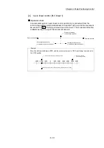
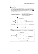
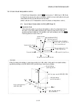
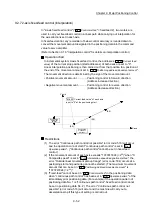
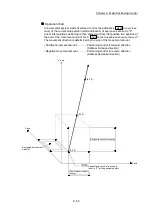
[2] 3-axis linear interpolation control (INC linear 3)
Operation chart
In the incremental system 3-axis linear interpolation control, the designated 3 axes
are used. Linear interpolation positioning is carried out from the current stop
position (start point address) to a position at the end of the movement amount set
in the "
Da.6
Positioning address/movement amount
". The movement direction is
determined the sign of the movement amount.
• Positive movement amount .............. Positioning control to forward direction
(Address increase direction)
• Negative movement amount ............. Positioning control to reverse direction
(Address decrease direction)
Z axis
movement
amount
X axis movement
amount
Y axis movement amount
Start point address (X1,Y1,Z1)
(current stop position)
Forward direction
Forward direction
Forward direction
Movement by linear interpolation
positioning of the X axis, Y axis and Z axis
Z
2
Y
2
X
2
Reverse direction
Reverse direction
Reverse direction
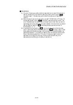
When the axis 1 movement amount is 10000, the axis 2 movement amount is 5000 and the axis
3 movement amount is 6000, positioning is carried out as follows.
Start point address
(current stop position)
Axis 1
Axis 3
Stop address after the positioning control
6000
Axis 2
Axis 3 movement
amount (6000)
5000
Axis 2 movement amount
(5000)
5000
10000
Axis 1 movement amount (10000)
Example
Summary of Contents for MELSEC-L Series
Page 2: ......
Page 30: ...MEMO ...
Page 70: ...2 10 Chapter 2 System Configuration MEMO ...
Page 83: ...3 13 Chapter 3 Specifications and Functions MEMO ...
Page 103: ...3 33 Chapter 3 Specifications and Functions MEMO ...
Page 107: ...3 37 Chapter 3 Specifications and Functions MEMO ...
Page 111: ...3 41 Chapter 3 Specifications and Functions MEMO ...
Page 115: ...3 45 Chapter 3 Specifications and Functions MEMO ...
Page 140: ...4 22 Chapter 4 Installation Wiring and Maintenance of the Product MEMO ...
Page 253: ...5 113 Chapter 5 Data Used for Positioning Control MEMO ...
Page 342: ...5 202 Chapter 5 Data Used for Positioning Control MEMO ...
Page 438: ...7 20 Chapter 7 Memory Configuration and Data Process MEMO ...
Page 440: ...MEMO ...
Page 485: ...9 25 Chapter 9 Major Positioning Control MEMO ...
Page 594: ...9 134 Chapter 9 Major Positioning Control MEMO ...
Page 624: ...10 30 Chapter 10 High Level Positioning Control MEMO ...
Page 656: ...11 32 Chapter 11 Manual Control MEMO ...
Page 690: ...12 34 Chapter 12 Expansion Control MEMO ...
Page 798: ...13 108 Chapter 13 Control Sub Functions MEMO ...
Page 866: ...14 68 Chapter 14 Common Functions MEMO ...
Page 884: ...15 18 Chapter 15 Dedicated Instructions MEMO ...
Page 899: ...16 15 Chapter 16 Troubleshooting MEMO ...
Page 1036: ...Appendix 88 Appendices MEMO ...
Page 1039: ......


