


3 - 18
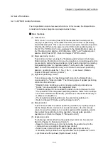
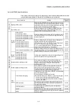
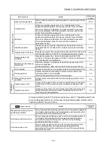
Chapter 3 Specifications and Functions
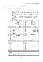
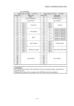
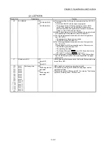
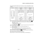
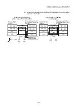
(3) LD77MS16
Signal direction: LD77MS16
PLC CPU
Signal direction: PLC CPU
LD77MS16
Device No.
Signal name
Device No.
Signal name
X0 READY Y0
PLC
READY
X1
Synchronization flag
Y1
All axis servo ON
X2
Use prohibited
Y2
Use prohibited
X3 Y3
X4 Y4
X5 Y5
X6 Y6
X7 Y7
X8 Y8
X9 Y9
XA YA
XB YB
XC YC
XD YD
XE YE
XF YF
X10 Axis
1
BUSY
Y10 Axis
1
Positioning start
X11 Axis
2
Y11 Axis
2
X12 Axis
3
Y12 Axis
3
X13 Axis
4
Y13 Axis
4
X14 Axis
5
Y14 Axis
5
X15 Axis
6
Y15 Axis
6
X16 Axis
7
Y16 Axis
7
X17 Axis
8
Y17 Axis
8
X18 Axis
9
Y18 Axis
9
X19 Axis
10
Y19 Axis
10
X1A Axis
11
Y1A Axis
11
X1B Axis
12
Y1B Axis
12
X1C Axis
13
Y1C Axis
13
X1D Axis
14
Y1D Axis
14
X1E Axis
15
Y1E Axis
15
X1F Axis
16
Y1F Axis
16
POINT
(1) For LD77MS16, M code ON signal, error detection signal, start complete signal and
positioning complete signal are assigned to the bit of "
Md.31
Status
".
(2) For LD77MS16, axis stop signal, forward run JOG start signal, reverse run JOG start
signal, execution prohibition flag are assigned to the buffer memory
Cd.180
to
Cd.183
.
Important
[Y2 to YF] and [X2 to XF] are used by the system, and cannot be used by the user.
If these devices are used, the operation of the LD77MS16 will not be guaranteed.
Summary of Contents for MELSEC-L Series
Page 2: ......
Page 30: ...MEMO ...
Page 70: ...2 10 Chapter 2 System Configuration MEMO ...
Page 83: ...3 13 Chapter 3 Specifications and Functions MEMO ...
Page 103: ...3 33 Chapter 3 Specifications and Functions MEMO ...
Page 107: ...3 37 Chapter 3 Specifications and Functions MEMO ...
Page 111: ...3 41 Chapter 3 Specifications and Functions MEMO ...
Page 115: ...3 45 Chapter 3 Specifications and Functions MEMO ...
Page 140: ...4 22 Chapter 4 Installation Wiring and Maintenance of the Product MEMO ...
Page 253: ...5 113 Chapter 5 Data Used for Positioning Control MEMO ...
Page 342: ...5 202 Chapter 5 Data Used for Positioning Control MEMO ...
Page 438: ...7 20 Chapter 7 Memory Configuration and Data Process MEMO ...
Page 440: ...MEMO ...
Page 485: ...9 25 Chapter 9 Major Positioning Control MEMO ...
Page 594: ...9 134 Chapter 9 Major Positioning Control MEMO ...
Page 624: ...10 30 Chapter 10 High Level Positioning Control MEMO ...
Page 656: ...11 32 Chapter 11 Manual Control MEMO ...
Page 690: ...12 34 Chapter 12 Expansion Control MEMO ...
Page 798: ...13 108 Chapter 13 Control Sub Functions MEMO ...
Page 866: ...14 68 Chapter 14 Common Functions MEMO ...
Page 884: ...15 18 Chapter 15 Dedicated Instructions MEMO ...
Page 899: ...16 15 Chapter 16 Troubleshooting MEMO ...
Page 1036: ...Appendix 88 Appendices MEMO ...
Page 1039: ......


