


5 - 36
Chapter 5 Data Used for Positioning Control
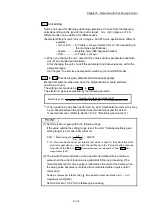
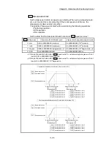
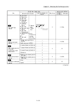
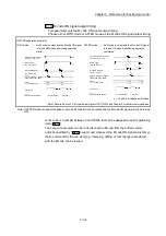
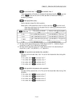
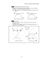
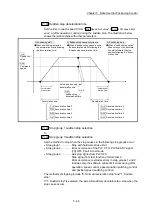
Pr.21
Current feed value during speed control
Specify whether you wish to enable or disable the update of "
Md.20
Current feed
value
" while operations are performed under the speed control (including the speed
control in speed-position and position-speed switching control).
0: The update of the current feed value is disabled
The current feed value will not change.
(The value at the beginning of the speed control
will be kept.)
1: The update of the current feed value is enabled
The current feed value will be updated.
(The current feed value will change from the
initial.)
2: The current feed value is cleared to zero
The current feed value will be set initially to zero
and change from zero while the speed control is
in effect.
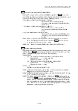
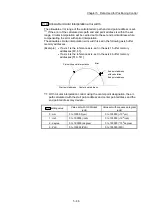
Note1: When the speed control is performed over two to four axes, the choice
between enabling and disabling the update of "
Md.20
Current feed value
"
depends on how the reference axis is set.
Note2: Set "1" to exercise speed-position switching control (ABS mode).
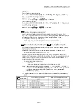
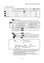
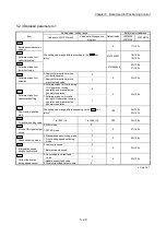
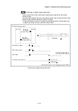
Pr.22
Input signal logic selection
Set the input signal logic that matches the signaling specification of the connected
external device, "
Cd.44
External input signal operation device
" or external input signal
of servo amplifier (upper/lower limit switch, near-point dog).
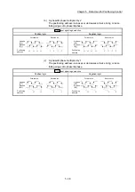
Negative logic
(1) The current is not flowed through the input signal contact.
(a) FLS, RLS .............. Limit signal ON
(b) DOG, DI, STOP .... Invalid
(2) The current is flowed through the input signal contact.
(a) FLS, RLS .............. Limit signal OFF
(b) DOG, DI, STOP .... Valid
Positive logic
Opposite the concept of negative logic.
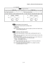
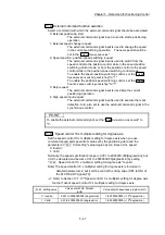
Note1: A mismatch in the signal logic will disable normal operation. Be careful of
this when you change from the default value.
Note2: Set the manual pulse generator input logic selection (b8) to axis 1. (Setting
of any of axes 2 to 4 is invalid.)
Note3: If the same external input signal is set to use to "
Pr.80
External input signal
selection
" or "
Pr.95
External command signal selection
" for the multiple axes in
the LD77MS16, "Input signal logic selection" of those axes should be the
same. Otherwise, the error "Input signal logic selection setting error" (error
code: 938) will occur when the PLC READY signal [Y0] is turned ON, and
the READY signal [X0] will not be turned ON.
Summary of Contents for MELSEC-L Series
Page 2: ......
Page 30: ...MEMO ...
Page 70: ...2 10 Chapter 2 System Configuration MEMO ...
Page 83: ...3 13 Chapter 3 Specifications and Functions MEMO ...
Page 103: ...3 33 Chapter 3 Specifications and Functions MEMO ...
Page 107: ...3 37 Chapter 3 Specifications and Functions MEMO ...
Page 111: ...3 41 Chapter 3 Specifications and Functions MEMO ...
Page 115: ...3 45 Chapter 3 Specifications and Functions MEMO ...
Page 140: ...4 22 Chapter 4 Installation Wiring and Maintenance of the Product MEMO ...
Page 253: ...5 113 Chapter 5 Data Used for Positioning Control MEMO ...
Page 342: ...5 202 Chapter 5 Data Used for Positioning Control MEMO ...
Page 438: ...7 20 Chapter 7 Memory Configuration and Data Process MEMO ...
Page 440: ...MEMO ...
Page 485: ...9 25 Chapter 9 Major Positioning Control MEMO ...
Page 594: ...9 134 Chapter 9 Major Positioning Control MEMO ...
Page 624: ...10 30 Chapter 10 High Level Positioning Control MEMO ...
Page 656: ...11 32 Chapter 11 Manual Control MEMO ...
Page 690: ...12 34 Chapter 12 Expansion Control MEMO ...
Page 798: ...13 108 Chapter 13 Control Sub Functions MEMO ...
Page 866: ...14 68 Chapter 14 Common Functions MEMO ...
Page 884: ...15 18 Chapter 15 Dedicated Instructions MEMO ...
Page 899: ...16 15 Chapter 16 Troubleshooting MEMO ...
Page 1036: ...Appendix 88 Appendices MEMO ...
Page 1039: ......


