


13 - 36
Chapter 13 Control Sub Functions
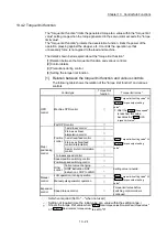
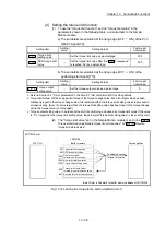
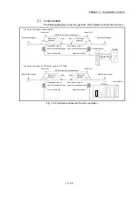
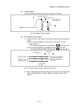
[2] Wiring the hardware stroke limit
When using the hardware stroke limit function, wire the signal terminals
corresponding to the upper/lower stroke limit of the device to be used as shown
in the following drawing.
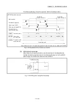
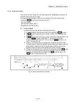
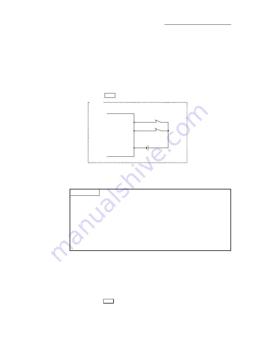
(1) External input signal of the servo amplifier
Refer to the manual of the servo amplifier to be used for details on input and
wiring of the signal.
Wire the MR-J3/MR-J4 series servo amplifier as shown in the following
drawing. As for the 24 V DC power supply, the direction of current can be
switched.
(When "
Pr.22
Input signal logic selection
" is set to the initial value)
Servo amplifier
DI1
(FLS)
DICOM
24 V DC
DI2
(RLS)
Example
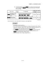
(2) External input signal via CPU (buffer memory of LD77MS)
For the wiring, refer to the manual of the input module to be used.
At MR-JE-B use, refer to Appendix 6.5 "Connection with MR-JE-B".
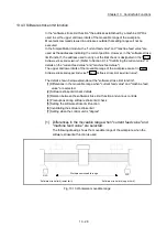
POINT
Wire the limit switch installed in the direction to which "Feed current value"
increases as upper limit switch and the limit switch installed in the limit switch
installed in the direction to which "Feed current value" decreases as lower limit
switch.
If inverting the install positions of upper/lower limit switches, hardware stroke limit
function cannot be operated properly. In addition, the servomotor does not stop.
The increase/decrease of "Feed current value" and the motor rotation
direction/movement direction can be changed by the parameters depending on the
servo amplifier. Refer to the servo amplifier instruction manual for details.
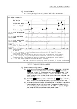
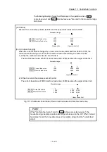
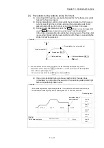
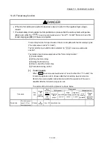
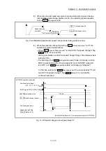
[3] Precautions during control
(1) If the machine is stopped outside the Simple Motion module control range
(outside the upper/lower limit switches), or if stopped by hardware stroke
limit detection, the starting for the "OPR control", "major positioning control",
and "high-level positioning control" and the control mode switching cannot
be executed. To carry out these types of control again, return the workpiece
to the Simple Motion module control range by a "JOG operation", "inching
operation" or "manual pulse generator operation".
(2) When
"
Pr.22
Input signal logic selection
" is set to the initial value, the Simple
Motion module cannot carry out the positioning control if FLS (limit switch for
upper limit) is separated from DICOM or RLS (limit switch for lower limit) is
separated from DICOM (including when wiring is not carried out).
Summary of Contents for MELSEC-L Series
Page 2: ......
Page 30: ...MEMO ...
Page 70: ...2 10 Chapter 2 System Configuration MEMO ...
Page 83: ...3 13 Chapter 3 Specifications and Functions MEMO ...
Page 103: ...3 33 Chapter 3 Specifications and Functions MEMO ...
Page 107: ...3 37 Chapter 3 Specifications and Functions MEMO ...
Page 111: ...3 41 Chapter 3 Specifications and Functions MEMO ...
Page 115: ...3 45 Chapter 3 Specifications and Functions MEMO ...
Page 140: ...4 22 Chapter 4 Installation Wiring and Maintenance of the Product MEMO ...
Page 253: ...5 113 Chapter 5 Data Used for Positioning Control MEMO ...
Page 342: ...5 202 Chapter 5 Data Used for Positioning Control MEMO ...
Page 438: ...7 20 Chapter 7 Memory Configuration and Data Process MEMO ...
Page 440: ...MEMO ...
Page 485: ...9 25 Chapter 9 Major Positioning Control MEMO ...
Page 594: ...9 134 Chapter 9 Major Positioning Control MEMO ...
Page 624: ...10 30 Chapter 10 High Level Positioning Control MEMO ...
Page 656: ...11 32 Chapter 11 Manual Control MEMO ...
Page 690: ...12 34 Chapter 12 Expansion Control MEMO ...
Page 798: ...13 108 Chapter 13 Control Sub Functions MEMO ...
Page 866: ...14 68 Chapter 14 Common Functions MEMO ...
Page 884: ...15 18 Chapter 15 Dedicated Instructions MEMO ...
Page 899: ...16 15 Chapter 16 Troubleshooting MEMO ...
Page 1036: ...Appendix 88 Appendices MEMO ...
Page 1039: ......


