

16 - 19
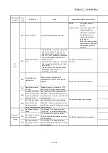
Chapter 16 Troubleshooting
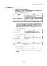
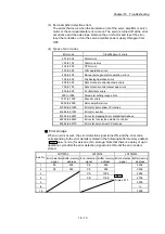
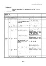
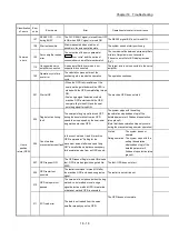
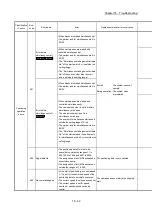
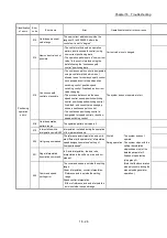
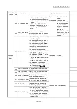
Related buffer memory address
Set range
(Setting with sequence program)
Remedy
LD77MS2
LD77MS4
LD77MS16
— —
—
Turn ON the PLC READY signal [Y0] with the BUSY signals
of all axes OFF.
— —
—
Do not request the start when the axis operation state is other
than "standby", "stop", and "step standby".
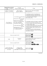
30100+200n 28400+100n
<Servo series>
0, 1, 3, 4, 6, 7, 32, 48, 64, 96, 97, 98, 99
Match the set series of the servo parameter "
Pr.100
Servo
series
" to the series of connected servo amplifier.
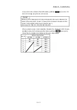
30100+200n 28400+100n
<Servo series>
97
Connect supported servo amplifier/driver.
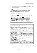
147 105
—
Review the content of the positioning or "
Pr.96
Operation cycle
setting
" longer than the current setting.
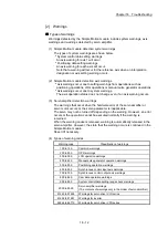
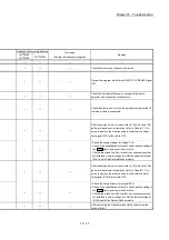
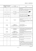
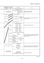
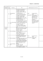
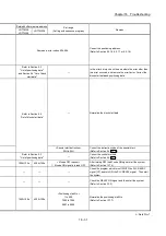
78+150n
<OPR retry>
0, 1
• Validate the OPR retry function (set value: 1). (Refer to
Section 13.2.1).
• Move the work piece from the current position (on OP) using
the manual control operation (refer to Chapter 11), then carry
out a machine OPR again.
74+150n
75+150n
<OPR speed>
1 to 1000000000 [PLS/s]
1 to 2000000000 [ 10
-2
mm/min or others]
• Lower the OPR speed.
• Increase the dog signal input time.
(Refer to Section 8.2.3)
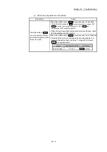
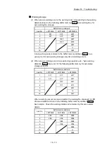
80+150n
81+150n
<Movement amount setting after near-
point dog ON>
0 to 2147483647
• Calculate the movement distance using a speed limit, OPR
speed, and deceleration time, and set the movement amount
after near-point dog ON so that the distance becomes a
deceleration distance or longer.
• Lower the OPR speed.
• Adjust the near-point dog position so that the movement
amount after near-point dog ON becomes longer. (Refer to
Section 8.2.4, 8.2.5)
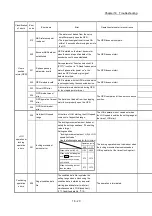
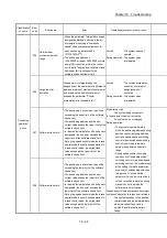
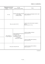
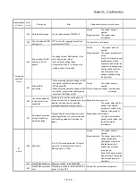
74+150n
75+150n
<OPR speed>
1 to 1000000000 [PLS/s]
1 to 2000000000 [ 10
-2
mm/min]
1500+100n 4300+100n
<Positioning start No.>
1 to 600, 7000 to 7004, 9001 to 9004
Execute the machine OPR (positioning start No. 9001). (Refer
to Section 8.2)
1500+100n 4300+100n
<Positioning start No.>
1 to 600, 7000 to 7004, 9001 to 9004
Start the machine OPR (positioning start No. 9001) again.
(Refer to Section 8.2)
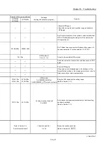
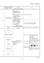
— —
—
Turn the motor more than one revolution using JOG or
positioning operation.
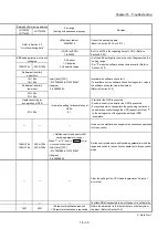
— —
—
• Execute OPR again.
• When the servo parameter "Function selection C-4 (PC17)"
is changed to "1: Not need to pass servo motor Z-phase after
power on", transfer the parameter from the Simple Motion
module to the servo amplifier and turn the power supply of
the servo amplifier OFF. Then, turn it ON and execute OPR
again.
n: Axis No.-1
Summary of Contents for MELSEC-L Series
Page 2: ......
Page 30: ...MEMO ...
Page 70: ...2 10 Chapter 2 System Configuration MEMO ...
Page 83: ...3 13 Chapter 3 Specifications and Functions MEMO ...
Page 103: ...3 33 Chapter 3 Specifications and Functions MEMO ...
Page 107: ...3 37 Chapter 3 Specifications and Functions MEMO ...
Page 111: ...3 41 Chapter 3 Specifications and Functions MEMO ...
Page 115: ...3 45 Chapter 3 Specifications and Functions MEMO ...
Page 140: ...4 22 Chapter 4 Installation Wiring and Maintenance of the Product MEMO ...
Page 253: ...5 113 Chapter 5 Data Used for Positioning Control MEMO ...
Page 342: ...5 202 Chapter 5 Data Used for Positioning Control MEMO ...
Page 438: ...7 20 Chapter 7 Memory Configuration and Data Process MEMO ...
Page 440: ...MEMO ...
Page 485: ...9 25 Chapter 9 Major Positioning Control MEMO ...
Page 594: ...9 134 Chapter 9 Major Positioning Control MEMO ...
Page 624: ...10 30 Chapter 10 High Level Positioning Control MEMO ...
Page 656: ...11 32 Chapter 11 Manual Control MEMO ...
Page 690: ...12 34 Chapter 12 Expansion Control MEMO ...
Page 798: ...13 108 Chapter 13 Control Sub Functions MEMO ...
Page 866: ...14 68 Chapter 14 Common Functions MEMO ...
Page 884: ...15 18 Chapter 15 Dedicated Instructions MEMO ...
Page 899: ...16 15 Chapter 16 Troubleshooting MEMO ...
Page 1036: ...Appendix 88 Appendices MEMO ...
Page 1039: ......


