


13 - 10
Chapter 13 Control Sub Functions
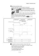
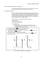
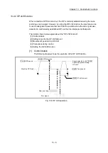
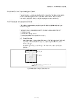
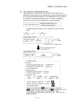
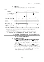
(2) OP shift operation at the "
Pr.47
Creep speed
"
(When "
Pr.56
Speed designation during OP shift
" is 1)
When the " Pr. 53 OP
shift amount" is negative
When the " Pr. 53 OP
shift amount" is positive
Pr. 44 OPR
direction
OP
Machine OPR start
Near-point dog
Zero signal
OP
Pr. 47 Creep
speed
V
Fig. 13.7 OP shift operation at the creep speed
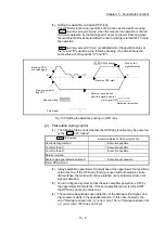
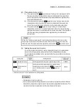
[4] Precautions during control
(1) The following data are set after the OP shift amount is complete.
OPR complete flag (
Md.31
Status
: b4)
Md.20
Current feed value
Md.21
Machine feed value
Md.26
Axis operation status
OPR request flag (
Md.31
Status
: b3) is reset after completion of the OP shift.
(2) "
Pr.53
OP shift amount
" is not added to "
Md.34
Movement amount after near-
point dog ON
". The movement amount immediately before the OP shift
operation, considering near-point dog ON as "0", is stored.
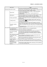
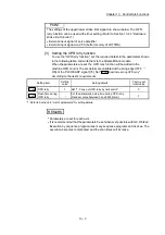
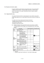
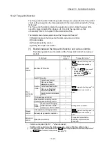
[5] Setting the OP shift function
To use the "OP shift function", set the required details in the parameters shown in
the following table, and write them to the Simple Motion module.
When the parameters are set, the OP shift function will be added to the machine
OPR control. The set details are validated at the rising edge (OFF
ON) of the
PLC READY signal [Y0].
Setting item
Setting
value
Setting details
Factory-set
initial value
Pr.53
OP shift amount
Set the shift amount during the OP shift.
0
Pr.56
Speed
designation
during OP shift
Select the speed during the OP shift
0:
Pr.46
OPR speed
1:
Pr.47
Creep speed
0
: Refer to Section 5.2 "List of parameters" for setting details.
REMARK
Parameters are set for each axis.
It is recommended that the parameters be set whenever possible with GX Works2.
Execution by sequence program uses many sequence programs and devices. The
execution becomes complicated, and the scan times will increase.
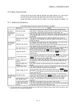
Summary of Contents for MELSEC-L Series
Page 2: ......
Page 30: ...MEMO ...
Page 70: ...2 10 Chapter 2 System Configuration MEMO ...
Page 83: ...3 13 Chapter 3 Specifications and Functions MEMO ...
Page 103: ...3 33 Chapter 3 Specifications and Functions MEMO ...
Page 107: ...3 37 Chapter 3 Specifications and Functions MEMO ...
Page 111: ...3 41 Chapter 3 Specifications and Functions MEMO ...
Page 115: ...3 45 Chapter 3 Specifications and Functions MEMO ...
Page 140: ...4 22 Chapter 4 Installation Wiring and Maintenance of the Product MEMO ...
Page 253: ...5 113 Chapter 5 Data Used for Positioning Control MEMO ...
Page 342: ...5 202 Chapter 5 Data Used for Positioning Control MEMO ...
Page 438: ...7 20 Chapter 7 Memory Configuration and Data Process MEMO ...
Page 440: ...MEMO ...
Page 485: ...9 25 Chapter 9 Major Positioning Control MEMO ...
Page 594: ...9 134 Chapter 9 Major Positioning Control MEMO ...
Page 624: ...10 30 Chapter 10 High Level Positioning Control MEMO ...
Page 656: ...11 32 Chapter 11 Manual Control MEMO ...
Page 690: ...12 34 Chapter 12 Expansion Control MEMO ...
Page 798: ...13 108 Chapter 13 Control Sub Functions MEMO ...
Page 866: ...14 68 Chapter 14 Common Functions MEMO ...
Page 884: ...15 18 Chapter 15 Dedicated Instructions MEMO ...
Page 899: ...16 15 Chapter 16 Troubleshooting MEMO ...
Page 1036: ...Appendix 88 Appendices MEMO ...
Page 1039: ......


