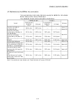


2 - 3
Chapter 2 System Configuration
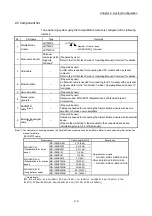
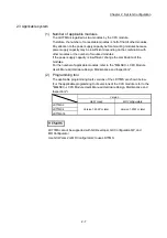
2.2 Component list
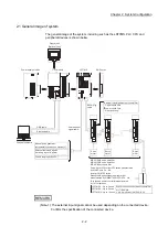
The positioning system using the Simple Motion module is configured of the following
devices.
No. Part
name
Type
Remarks
1
Simple Motion
module
LD77MS2
LD77MS
Number of control axes
MS: SSCNET (/H)model
LD77MS4
LD77MS16
2 Personal
computer
Personal
computer which
supports
Windows
R
(Prepared by user)
Refer to the "GX Works2 Version1 Operating Manual (Common)" for details.
3 USB
cable
–
(Prepared by user)
A USB cable is needed for connecting the CPU module with a personal
computer.
Refer to the "GX Works2 Version1 Operating Manual (Common)" for details.
4 Ethernet
cable
–
(Prepared by user)
An Ethernet cable is needed for connecting the CPU module with a personal
computer. Refer to the "GX Works2 Version1 Operating Manual (Common)"
for details.
5 Servo
amplifier
–
(Prepared by user)
6
Manual pulse
generator
–
(Prepared by user)
Recommended: MR-HDP01 (Manufactured by Mitsubishi Electric
Corporation)
7
SSCNET
cable
(Note-1)
–
(Prepared by user)
Cables are needed for connecting the Simple Motion module with a servo
amplifier, or between servo amplifiers.
8
External input signal
cable
(Note-1)
–
(Prepared by user)
Cables are needed for connecting the Simple Motion module with an external
device.
(Prepare them referring to the manuals for the connected devices and
information given in 3.4.2 of this manual.)
(Note-1): The cables for connecting between the Simple Motion module and servo amplifiers. Refer to each servo amplifier instruction
manual for details.
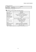
[SSCNET cable]
Model name
Cable length [m(ft.)]
Description
MR-J3BUS_M
(Standard cord for inside
panel)
MR-J3BUS015M 0.15
(0.49)
• Simple Motion module
MR-J4(W)-B/MR-JE-B/MR-J3(W)-B
• MR-J4(W)-B/MR-JE-B/MR-J3(W)-B
MR-J4(W)-B/MR-JE-B/MR-J3(W)-B
MR-J3BUS03M 0.3
(0.98)
MR-J3BUS05M 0.5
(1.64)
MR-J3BUS1M 1
(3.28)
MR-J3BUS3M 3
(9.84)
MR-J3BUS_M-A
(Standard cable for outside
panel)
MR-J3BUS5M-A 5
(16.40)
MR-J3BUS10M-A 10
(32.81)
MR-J3BUS20M-A 20
(65.62)
MR-J3BUS_M-B
(Long distance cable)
MR-J3BUS30M-B 30
(98.43)
MR-J3BUS40M-B 40
(131.23)
MR-J3BUS50M-B 50
(164.04)
_ = Cable length
(015: 0.15m (0.49ft.), 03: 0.3m (0.98ft.), 05: 0.5m (1.64ft.), 1: 1m (3.28ft.), 3: 3m (9.84ft.), 5: 5m (16.40ft.), 10: 10m
(32.81ft.), 20: 20m (65.62ft.), 30: 30m (98.43ft.), 40: 40m (131.23ft.), 50: 50m (164.04ft.) )
Summary of Contents for MELSEC-L Series
Page 2: ......
Page 30: ...MEMO ...
Page 70: ...2 10 Chapter 2 System Configuration MEMO ...
Page 83: ...3 13 Chapter 3 Specifications and Functions MEMO ...
Page 103: ...3 33 Chapter 3 Specifications and Functions MEMO ...
Page 107: ...3 37 Chapter 3 Specifications and Functions MEMO ...
Page 111: ...3 41 Chapter 3 Specifications and Functions MEMO ...
Page 115: ...3 45 Chapter 3 Specifications and Functions MEMO ...
Page 140: ...4 22 Chapter 4 Installation Wiring and Maintenance of the Product MEMO ...
Page 253: ...5 113 Chapter 5 Data Used for Positioning Control MEMO ...
Page 342: ...5 202 Chapter 5 Data Used for Positioning Control MEMO ...
Page 438: ...7 20 Chapter 7 Memory Configuration and Data Process MEMO ...
Page 440: ...MEMO ...
Page 485: ...9 25 Chapter 9 Major Positioning Control MEMO ...
Page 594: ...9 134 Chapter 9 Major Positioning Control MEMO ...
Page 624: ...10 30 Chapter 10 High Level Positioning Control MEMO ...
Page 656: ...11 32 Chapter 11 Manual Control MEMO ...
Page 690: ...12 34 Chapter 12 Expansion Control MEMO ...
Page 798: ...13 108 Chapter 13 Control Sub Functions MEMO ...
Page 866: ...14 68 Chapter 14 Common Functions MEMO ...
Page 884: ...15 18 Chapter 15 Dedicated Instructions MEMO ...
Page 899: ...16 15 Chapter 16 Troubleshooting MEMO ...
Page 1036: ...Appendix 88 Appendices MEMO ...
Page 1039: ......


