


5 - 44
Chapter 5 Data Used for Positioning Control
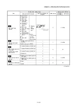
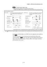
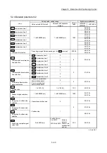
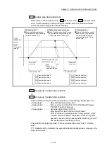
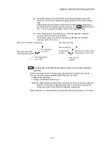
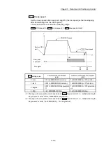
Pr.36
Sudden stop deceleration time
Set the time to reach speed 0 from "
Pr.8
Speed limit value
" ("
Pr.31
JOG speed limit
value
" at JOG operation control) during the sudden stop. The illustration below
shows the relationships with other parameters.
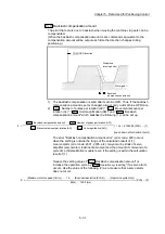
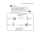
When positioning is started,
the acceleration starts following
the "acceleration time".
1) Positioning start
2) Sudden stop cause occurrence
When a "sudden stop cause" occurs,
the deceleration starts following the
"sudden stop deceleration time".
3) Positioning stop
When a "sudden stop cause"
does not occur, the decelera-
tion starts toward the stop
position following the "decel-
eration time".
Actual accel-
eration time
Actual sudden stop
deceleration time
Acceleration time
Actual decel-
eration time
Deceleration time
Speed limit
value
Pr.8
Command
speed
Da.8
Pr.36
Sudden stop
deceleration time
Acceleration time 0
Pr.9
Acceleration time 1
Pr.25
Acceleration time 2
Pr.26
Acceleration time 3
Pr.27
Deceleration time 0
Pr.10
Deceleration time 1
Pr.28
Deceleration time 2
Pr.29
Deceleration time 3
Pr.30
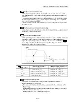
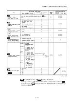
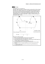
Pr.37
Stop group 1 sudden stop selection
to
Pr.39
Stop group 3 sudden stop selection
Set the method to stop when the stop causes in the following stop groups occur.
Stop group 1 ............. Stop with hardware stroke limit
Stop group 2 ............. Error occurrence of the PLC CPU, PLC READY signal
[Y0] OFF, Fault in test mode
Stop group 3 ............. Axis stop signal from PLC CPU
Stop signal from test function of GX Works2
Error occurrence (excludes errors in stop groups 1 and 2:
includes only the software stroke limit errors during JOG
operation, speed control, speed-position switching control,
and position-speed switching control)
The methods of stopping include "0: Normal deceleration stop" and "1: Sudden
stop".
If "1: Sudden stop" is selected, the axis will suddenly decelerate to a stop when the
stop cause occurs.
Summary of Contents for MELSEC-L Series
Page 2: ......
Page 30: ...MEMO ...
Page 70: ...2 10 Chapter 2 System Configuration MEMO ...
Page 83: ...3 13 Chapter 3 Specifications and Functions MEMO ...
Page 103: ...3 33 Chapter 3 Specifications and Functions MEMO ...
Page 107: ...3 37 Chapter 3 Specifications and Functions MEMO ...
Page 111: ...3 41 Chapter 3 Specifications and Functions MEMO ...
Page 115: ...3 45 Chapter 3 Specifications and Functions MEMO ...
Page 140: ...4 22 Chapter 4 Installation Wiring and Maintenance of the Product MEMO ...
Page 253: ...5 113 Chapter 5 Data Used for Positioning Control MEMO ...
Page 342: ...5 202 Chapter 5 Data Used for Positioning Control MEMO ...
Page 438: ...7 20 Chapter 7 Memory Configuration and Data Process MEMO ...
Page 440: ...MEMO ...
Page 485: ...9 25 Chapter 9 Major Positioning Control MEMO ...
Page 594: ...9 134 Chapter 9 Major Positioning Control MEMO ...
Page 624: ...10 30 Chapter 10 High Level Positioning Control MEMO ...
Page 656: ...11 32 Chapter 11 Manual Control MEMO ...
Page 690: ...12 34 Chapter 12 Expansion Control MEMO ...
Page 798: ...13 108 Chapter 13 Control Sub Functions MEMO ...
Page 866: ...14 68 Chapter 14 Common Functions MEMO ...
Page 884: ...15 18 Chapter 15 Dedicated Instructions MEMO ...
Page 899: ...16 15 Chapter 16 Troubleshooting MEMO ...
Page 1036: ...Appendix 88 Appendices MEMO ...
Page 1039: ......


