


3 - 31
Chapter 3 Specifications and Functions
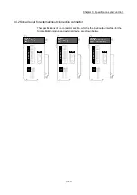
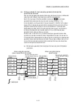
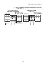
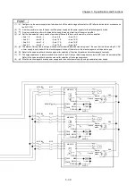
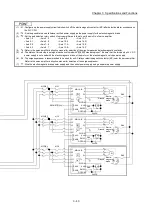
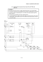
(4) Wiring example for manual pulse generator/incremental
synchronous encoder
Wire the manual pulse generator/incremental synchronous encoder of differential
output type and voltage output type/open-collector type as follows.
Switch the input type of the Simple Motion module by "
Pr.89
Manual pulse
generator/Incremental synchronous encoder input type selection". It is
recommended to use the external 5 V power supply (5 V DC±5%) for the power
supply of the manual pulse generator/incremental synchronous encoder. When
using the external power supply, do not connect with the 5 V terminal of the
Simple Motion module. When using the internal power supply, connect the 5 V
terminal of the Simple Motion module and the 5 V (+) of the manual pulse
generator/incremental synchronous encoder.
In either case, connect the 0 V (-) of the manual pulse generator/incremental
synchronous encoder and the SG of the Simple Motion module. Do not use the
5 V terminal of the Simple Motion module except for connecting the manual pulse
generator/incremental synchronous encoder. It may cause a failure. Also, do not
connect the manual pulse generator/incremental synchronous encoder whose
current consumption exceeds 200 mA.
(a) Manual pulse generator/Incremental synchronous encoder of differential
output type
Simple Motion
module
HAH (A+)
HAL (A-)
HBH (B+)
HBL (B-)
5 V
0 V
HAH (A+)
HAL (A-)
HBH (B+)
HBL (B-)
5 V
SG
HAH (A+)
HAL (A-)
HBH (B+)
HBL
(B-)
5 V
SG
HAH (A+)
HAL
(A-)
HBH (B+)
HBL
(B-)
5 V
0 V
When using the internal
Manual pulse generator/
Incremental synchronous
Manual pulse generator/
Incremental synchronous
External 5 V
Twisted pair
FG
FG
Shield
FG
FG
Shield
encoder
encoder
power supply
power supply
When using the external
power supply (Recommended)
Simple Motion
module
Summary of Contents for MELSEC-L Series
Page 2: ......
Page 30: ...MEMO ...
Page 70: ...2 10 Chapter 2 System Configuration MEMO ...
Page 83: ...3 13 Chapter 3 Specifications and Functions MEMO ...
Page 103: ...3 33 Chapter 3 Specifications and Functions MEMO ...
Page 107: ...3 37 Chapter 3 Specifications and Functions MEMO ...
Page 111: ...3 41 Chapter 3 Specifications and Functions MEMO ...
Page 115: ...3 45 Chapter 3 Specifications and Functions MEMO ...
Page 140: ...4 22 Chapter 4 Installation Wiring and Maintenance of the Product MEMO ...
Page 253: ...5 113 Chapter 5 Data Used for Positioning Control MEMO ...
Page 342: ...5 202 Chapter 5 Data Used for Positioning Control MEMO ...
Page 438: ...7 20 Chapter 7 Memory Configuration and Data Process MEMO ...
Page 440: ...MEMO ...
Page 485: ...9 25 Chapter 9 Major Positioning Control MEMO ...
Page 594: ...9 134 Chapter 9 Major Positioning Control MEMO ...
Page 624: ...10 30 Chapter 10 High Level Positioning Control MEMO ...
Page 656: ...11 32 Chapter 11 Manual Control MEMO ...
Page 690: ...12 34 Chapter 12 Expansion Control MEMO ...
Page 798: ...13 108 Chapter 13 Control Sub Functions MEMO ...
Page 866: ...14 68 Chapter 14 Common Functions MEMO ...
Page 884: ...15 18 Chapter 15 Dedicated Instructions MEMO ...
Page 899: ...16 15 Chapter 16 Troubleshooting MEMO ...
Page 1036: ...Appendix 88 Appendices MEMO ...
Page 1039: ......


