


13 - 30
Chapter 13 Control Sub Functions
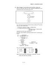
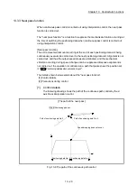
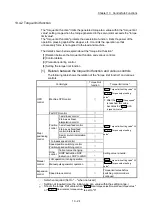
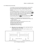
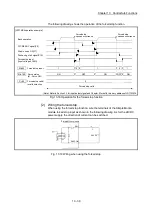
[2] Software stroke limit check details
Check details
Processing when
an error occurs
1)
An error shall occur if the current value
*1
is outside the software stroke
limit range
*2
.
(Check "
Md.20
Current feed value
" or "
Md.21
Machine feed value
".)
The error
"Software stroke
limit +" (error
code: 507) or
"Software stroke
limit -" (error code:
508) will occur.
2)
An error shall occur if the command address is outside the software
stroke limit range.
(Check "
Da.6
Positioning address/movement amount
".)
1: Check whether the "
Md.20
Current feed value
" or "
Md.21
Machine feed value
" is set in "
Pr.14
Software stroke limit selection
".
2: Moveable range from the "
Pr.12
Software stroke limit upper limit value
" to the "
Pr.13
Software
stroke limit lower limit value
".
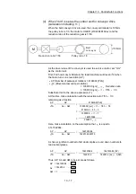
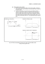
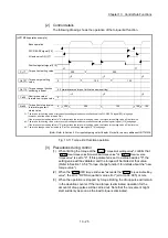
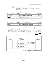
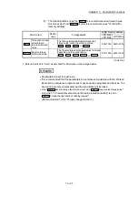
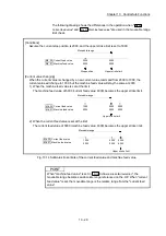
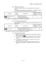
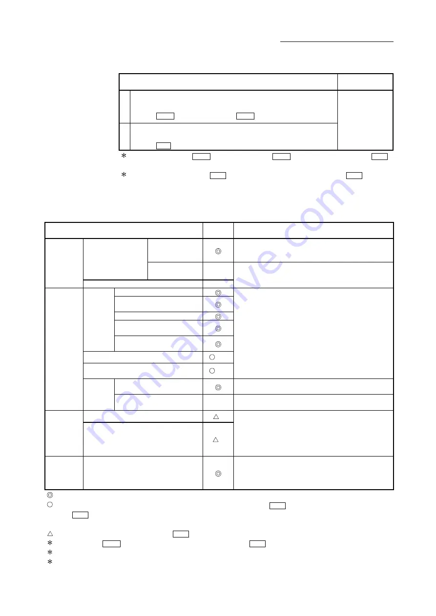
[3] Relation between the software stroke limit function and various
controls
Control type
Limit
check
Processing at check
OPR control
Machine OPR control
Data set method
The current value will not be changed if the home
position address is outside the software stroke limit
range.
Other than "Data
set method"
–
Check not carried out.
Fast OPR control
–
Major
positioning
control
Position
control
1-axis linear control
Checks 1) and 2) in the previous section [2] are carried
out.
For speed control : The axis decelerates to a stop
when it exceeds the software
stroke limit range.
For position control: The axis comes to an immediate
stop when it exceeds the software
stroke limit range.
2 to 4-axes axis linear
interpolation control
1-axis fixed-feed control
2 to 4-axes fixed-feed control
(interpolation)
2-axis circular interpolation
control
1 to 4-axes speed control
*1, *2
Speed-position switching control
Position-speed switching control
*1, *2
Other
control
Current value changing
The current value will not be changed if the new
current value is outside the software stroke limit range.
JUMP instruction, NOP
instruction, LOOP to LEND
–
Check not carried out.
Manual
control
JOG operation, Inching operation
*3
Check 1) in the previous section [2] is carried out.
The machine will carry out a deceleration stop when
the software stroke limit range is exceeded. If the
address is outside the software stroke limit range, the
operation can only be started toward the moveable
range.
Manual pulse generator operation
* 3
Expansion
control
Speed-torque control
Check 1) in the previous section [2] is carried out.
The mode switches to the position control mode when
the software stroke limit range is exceeded, and the
operation immediately stops.
: Check valid
: Check is not made when the current feed value is not updated (Refer to
Pr.21
) at the setting of "current feed value"
in "
Pr.14
Software stroke limit selection
" during speed control.
– : Check not carried out (check invalid).
: Valid only when "0: valid" is set in the "
Pr.15
Software stroke limit valid/invalid setting
".
1 : The value in "
Md.20
Current feed value
" will differ according to the "
Pr.21
Current feed value during speed control
" setting.
2: When the unit is "degree", check is not made during speed control.
3: When the unit is "degree", check is not carried out.
Summary of Contents for MELSEC-L Series
Page 2: ......
Page 30: ...MEMO ...
Page 70: ...2 10 Chapter 2 System Configuration MEMO ...
Page 83: ...3 13 Chapter 3 Specifications and Functions MEMO ...
Page 103: ...3 33 Chapter 3 Specifications and Functions MEMO ...
Page 107: ...3 37 Chapter 3 Specifications and Functions MEMO ...
Page 111: ...3 41 Chapter 3 Specifications and Functions MEMO ...
Page 115: ...3 45 Chapter 3 Specifications and Functions MEMO ...
Page 140: ...4 22 Chapter 4 Installation Wiring and Maintenance of the Product MEMO ...
Page 253: ...5 113 Chapter 5 Data Used for Positioning Control MEMO ...
Page 342: ...5 202 Chapter 5 Data Used for Positioning Control MEMO ...
Page 438: ...7 20 Chapter 7 Memory Configuration and Data Process MEMO ...
Page 440: ...MEMO ...
Page 485: ...9 25 Chapter 9 Major Positioning Control MEMO ...
Page 594: ...9 134 Chapter 9 Major Positioning Control MEMO ...
Page 624: ...10 30 Chapter 10 High Level Positioning Control MEMO ...
Page 656: ...11 32 Chapter 11 Manual Control MEMO ...
Page 690: ...12 34 Chapter 12 Expansion Control MEMO ...
Page 798: ...13 108 Chapter 13 Control Sub Functions MEMO ...
Page 866: ...14 68 Chapter 14 Common Functions MEMO ...
Page 884: ...15 18 Chapter 15 Dedicated Instructions MEMO ...
Page 899: ...16 15 Chapter 16 Troubleshooting MEMO ...
Page 1036: ...Appendix 88 Appendices MEMO ...
Page 1039: ......


