


13 - 69
Chapter 13 Control Sub Functions
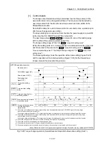
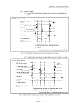
[5] Control details
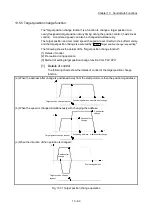
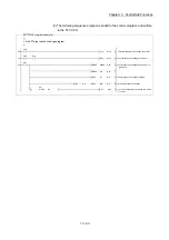
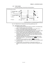
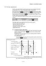
(1) The following drawing shows a step operation during a "deceleration unit
step".
[LD77MS4 operation example]
Positioning
Cd. 35 Step valid flag
Positioning data No.
Da. 1 Operation pattern
No.10
11
No.11
01
No positioning data No. unit, so operation pattern
becomes one step of unit for carrying out automatic
deceleration.
t
OFF
ON
ON
OFF
V
ON
OFF
OFF
ON
BUSY signal
Positioning start signal
Positioning complete signal
[Y10, Y11, Y12, Y13]
[XC, XD, XE, XF]
[X14, X15, X16, X17]
(Note): Refer to Section 3.3 for input/output signal of LD77MS16.
Fig. 13.35 Operation during step execution by deceleration unit step
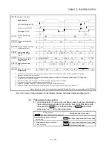
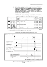
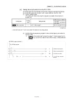
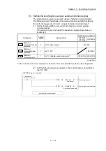
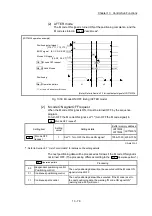
(2) The following drawing shows a step operation during a "data No. unit step".
[LD77MS4 operation example]
Cd. 36 Step start information
Cd. 35 Step valid flag
No.10
11
No.11
01
Operation pattern becomes one step of positioning data No. unit,
regardless of continuous path control (11).
00H
00H
OFF
ON
OFF
OFF
ON
ON
ON
OFF
t
V
Positioning
Positioning data No.
Da. 1 Operation pattern
BUSY signal
Positioning start signal
Positioning complete signal
[XC, XD, XE, XF]
[Y10, Y11, Y12, Y13]
[X14, X15, X16, X17]
01H
(Note): Refer to Section 3.3 for input/output signal of LD77MS16.
Fig. 13.36 Operation during step execution positioning data No. unit step
Summary of Contents for MELSEC-L Series
Page 2: ......
Page 30: ...MEMO ...
Page 70: ...2 10 Chapter 2 System Configuration MEMO ...
Page 83: ...3 13 Chapter 3 Specifications and Functions MEMO ...
Page 103: ...3 33 Chapter 3 Specifications and Functions MEMO ...
Page 107: ...3 37 Chapter 3 Specifications and Functions MEMO ...
Page 111: ...3 41 Chapter 3 Specifications and Functions MEMO ...
Page 115: ...3 45 Chapter 3 Specifications and Functions MEMO ...
Page 140: ...4 22 Chapter 4 Installation Wiring and Maintenance of the Product MEMO ...
Page 253: ...5 113 Chapter 5 Data Used for Positioning Control MEMO ...
Page 342: ...5 202 Chapter 5 Data Used for Positioning Control MEMO ...
Page 438: ...7 20 Chapter 7 Memory Configuration and Data Process MEMO ...
Page 440: ...MEMO ...
Page 485: ...9 25 Chapter 9 Major Positioning Control MEMO ...
Page 594: ...9 134 Chapter 9 Major Positioning Control MEMO ...
Page 624: ...10 30 Chapter 10 High Level Positioning Control MEMO ...
Page 656: ...11 32 Chapter 11 Manual Control MEMO ...
Page 690: ...12 34 Chapter 12 Expansion Control MEMO ...
Page 798: ...13 108 Chapter 13 Control Sub Functions MEMO ...
Page 866: ...14 68 Chapter 14 Common Functions MEMO ...
Page 884: ...15 18 Chapter 15 Dedicated Instructions MEMO ...
Page 899: ...16 15 Chapter 16 Troubleshooting MEMO ...
Page 1036: ...Appendix 88 Appendices MEMO ...
Page 1039: ......


