


8 - 7
Chapter 8 OPR Control
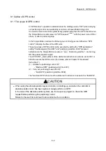
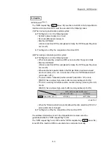
8.2.2 Machine OPR method
The method by which the machine OP is established (method for judging the OP and
machine OPR completion) is designated in the machine OPR according to the
configuration and application of the positioning method.
The following table shows the methods that can be used for this OPR method.
(The OPR method is one of the items set in the OPR parameters. It is set in "
Pr.43
OPR method
" of the basic parameters for OPR.)
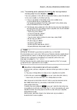
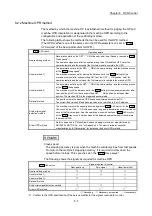
Pr.43
OPR method
Operation details
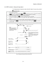
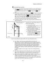
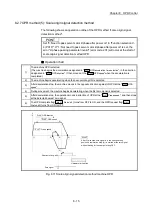
Near-point dog method
Deceleration starts by the OFF
ON of the near-point dog. (Speed is reduced to "
Pr.47
Creep speed".)
The operation stops once after the near-point dog turns ON and then OFF. Later the
operation restarts and then stops at the first zero signal to complete the OPR.
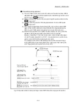
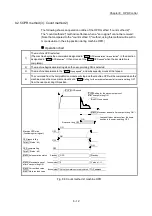
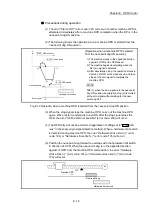
Count method 1)
The deceleration starts by the OFF
ON of the near-point dog, and the machine moves
at the "
Pr.47
Creep speed".
The machine stops once after moving the distance set in the "
Pr.50
Setting for the
movement amount after near-point dog ON" from the OFF
ON position. Later the
operation restarts and then stops at the first zero point to complete the machine OPR.
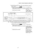
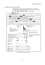
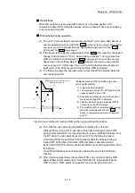
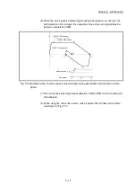
Count method 2)
The deceleration starts by the OFF
ON of the near-point dog, and the machine moves
at the "
Pr.47
Creep speed.
The machine moves the distance set in the "
Pr.50
Setting for the movement amount after
near-point dog ON" from the near-point dog OFF
ON position, and stops at that
position. The machine OPR is then regarded as completed.
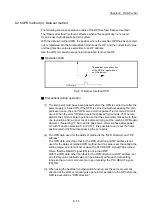
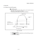
Data set method
The position where the machine OPR has been performed becomes an OP.
The current feed value and feed machine value are overwritten to the OP address.
Scale origin signal
detection method
The machine moves in the opposite direction against of "
Pr.44
OPR direction
" at the "
Pr.46
OPR speed
" by the OFF
ON of the near-point dog, and a deceleration stop is carried out
once at the first zero signal. Later the operation moves in direction of "
Pr.44
OPR direction
"
at the "
Pr.47
Creep speed
", and then stops at the detected nearest zero point to complete
the machine OPR.
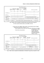
Driver OPR method
Refer to Appendix 6.3 "AlphaStep/5-phase stepping motor driver manufactured by
ORIENTAL MOTOR Co., Ltd." or Appendix 6.4 "IAI electric actuator controller
manufactured by IAI Corporation" for details on the driver OPR method.
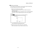
REMARK
Creep speed
The stopping accuracy is poor when the machine suddenly stops from fast speeds.
To improve the machine's stopping accuracy, it is required to slow down the
speed before it stops. This speed is set in the "
Pr.47
Creep speed
".
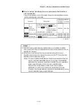
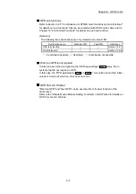
The following shows the signals as required for machine OPR.
Pr.43
OPR method
Signals required for control
Near-point dog
Zero signal
Upper/lower limit
Near-point dog method
Count method 1)
Count method 2)
Data set method
Scale origin signal detection method
Driver OPR method
*1
*1
*1
: Necessary, : Necessary as required,
: Unnecessary
1: Confirm to the OPR specification of the servo amplifier for the signals required for control.
Summary of Contents for MELSEC-L Series
Page 2: ......
Page 30: ...MEMO ...
Page 70: ...2 10 Chapter 2 System Configuration MEMO ...
Page 83: ...3 13 Chapter 3 Specifications and Functions MEMO ...
Page 103: ...3 33 Chapter 3 Specifications and Functions MEMO ...
Page 107: ...3 37 Chapter 3 Specifications and Functions MEMO ...
Page 111: ...3 41 Chapter 3 Specifications and Functions MEMO ...
Page 115: ...3 45 Chapter 3 Specifications and Functions MEMO ...
Page 140: ...4 22 Chapter 4 Installation Wiring and Maintenance of the Product MEMO ...
Page 253: ...5 113 Chapter 5 Data Used for Positioning Control MEMO ...
Page 342: ...5 202 Chapter 5 Data Used for Positioning Control MEMO ...
Page 438: ...7 20 Chapter 7 Memory Configuration and Data Process MEMO ...
Page 440: ...MEMO ...
Page 485: ...9 25 Chapter 9 Major Positioning Control MEMO ...
Page 594: ...9 134 Chapter 9 Major Positioning Control MEMO ...
Page 624: ...10 30 Chapter 10 High Level Positioning Control MEMO ...
Page 656: ...11 32 Chapter 11 Manual Control MEMO ...
Page 690: ...12 34 Chapter 12 Expansion Control MEMO ...
Page 798: ...13 108 Chapter 13 Control Sub Functions MEMO ...
Page 866: ...14 68 Chapter 14 Common Functions MEMO ...
Page 884: ...15 18 Chapter 15 Dedicated Instructions MEMO ...
Page 899: ...16 15 Chapter 16 Troubleshooting MEMO ...
Page 1036: ...Appendix 88 Appendices MEMO ...
Page 1039: ......


