


13 - 25
Chapter 13 Control Sub Functions
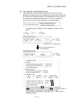
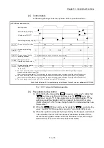
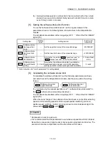
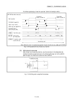
[2] Control details
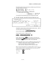
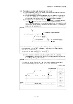
The following drawing shows the operation of the torque limit function.
[LD77MS4 operation example]
300
250
100
150
0
0
0
300
300
100
150
150
1: The torque limit setting value or torque output setting value becomes effective at the PLC READY signal [Y0] rising edge
(however, after the servo is turned ON.)
If the torque output setting value is "0" or larger than the torque limit setting value, the torque limit setting value will be its value.
2: The torque limit setting value or torque output setting value becomes effective at the positioning start signal [Y10] rising edge.
If the torque output setting value is "0" or larger than the torque limit setting value, the torque limit setting value will be its value.
3: The torque change value is cleared to "0" at the positioning start signal [Y10] rising edge.
Each operation
PLC READY signal [Y0]
All axis servo ON [Y1]
Torque limit setting value
Pr.17
Torque output setting
value
Cd.101
New torque value/
forward new torque value
Cd.22
Torque limit stored value/
forward torque limit
stored value
Md.35
1
1
2
2
2
3
3
Torque change function
switching request
Cd.112
3
Positioning start signal [Y10]
0 (Forward/reverse torque limit value same setting)
(Note): Refer to Section 3.3 for input/output signal or Chapter 5 for buffer memory address of LD77MS16.
Fig. 13.11 Torque limit function operation
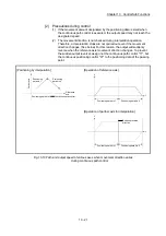
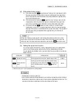
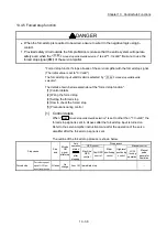
[3] Precautions during control
(1) When limiting the torque at the "
Pr.17
Torque limit setting value
", confirm that
"
Cd.22
New torque value/forward new torque value
" or "
Cd.113
New reverse
torque value
" is set to "0". If this parameter is set to a value besides "0", the
setting value will be validated, and the torque will be limited at that value.
(Refer to Section 13.5.4 "Torque change function" for details about the "new
torque value".)
(2) When
the
"
Pr.54
OPR torque limit value
" exceeds the "
Pr.17
Torque limit setting
value
", the error "OPR torque limit value error" (error code: 995) occurs.
(3) When the operation is stopped by torque limiting, the droop pulse will remain
in the deviation counter. If the load torque is eliminated, operation for the
amount of droop pulses will be carried out. Note that the movement might
start suddenly as soon as the load torque is eliminated.
Summary of Contents for MELSEC-L Series
Page 2: ......
Page 30: ...MEMO ...
Page 70: ...2 10 Chapter 2 System Configuration MEMO ...
Page 83: ...3 13 Chapter 3 Specifications and Functions MEMO ...
Page 103: ...3 33 Chapter 3 Specifications and Functions MEMO ...
Page 107: ...3 37 Chapter 3 Specifications and Functions MEMO ...
Page 111: ...3 41 Chapter 3 Specifications and Functions MEMO ...
Page 115: ...3 45 Chapter 3 Specifications and Functions MEMO ...
Page 140: ...4 22 Chapter 4 Installation Wiring and Maintenance of the Product MEMO ...
Page 253: ...5 113 Chapter 5 Data Used for Positioning Control MEMO ...
Page 342: ...5 202 Chapter 5 Data Used for Positioning Control MEMO ...
Page 438: ...7 20 Chapter 7 Memory Configuration and Data Process MEMO ...
Page 440: ...MEMO ...
Page 485: ...9 25 Chapter 9 Major Positioning Control MEMO ...
Page 594: ...9 134 Chapter 9 Major Positioning Control MEMO ...
Page 624: ...10 30 Chapter 10 High Level Positioning Control MEMO ...
Page 656: ...11 32 Chapter 11 Manual Control MEMO ...
Page 690: ...12 34 Chapter 12 Expansion Control MEMO ...
Page 798: ...13 108 Chapter 13 Control Sub Functions MEMO ...
Page 866: ...14 68 Chapter 14 Common Functions MEMO ...
Page 884: ...15 18 Chapter 15 Dedicated Instructions MEMO ...
Page 899: ...16 15 Chapter 16 Troubleshooting MEMO ...
Page 1036: ...Appendix 88 Appendices MEMO ...
Page 1039: ......


