


Appendix - 46
Appendices
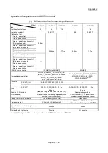
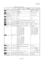
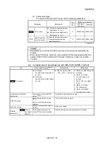
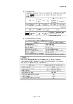
Appendix 4 Comparisons with LD77MH models
(1) Differences of performance specifications
Model
Item
LD77MS2 LD77MS4 LD77MS16
LD77MH4
LD77MH16
Number of control axes
2
4
16
4
16
Operation cycle [ms]
0.88/1.77
0.88
0.88/1.77
Starting time [ms]
0.88ms
0.88ms 1.77ms
0.88ms
1.77ms
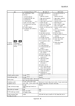
1-axis linear control
1-axis speed control
2-axis linear interpolation control
(Composite speed)
2-axis linear interpolation control
(Reference axis speed)
2-axis circular interpolation control
2-axis speed control
3-axis linear interpolation control
(Composite speed)
—
3-axis linear interpolation control
(Reference axis speed)
3-axis speed control
4-axis linear interpolation control
4-axis speed control
SSCNET communication
SSCNET /H or SSCNET
SSCNET
Compatible servo amplifier
MR-J4-_B_/MR-J4W_-_B/MR-J4-_B_-RJ/
MR-J3-_B_/MR-J3W-_B/MR-J3-_B_-RJ006/
MR-J3-_BS_/MR-J3-_B_-RJ004/
MR-J3-_B-RJ080W/MR-JE-_B
MR-J3-_B_/MR-J3W-_B/MR-J3-_B_-RJ006/
MR-J3-_BS_/MR-J3-_B_-RJ004/
MR-J3-_B-RJ080W
(Note-1)
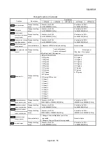
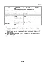
Controlled
servo
parameter
group
SSCNET /H
PA, PB, PC, PD, PE, PS, PF, Po, PL
—
SSCNET
PA, PB, PC, PD, PE, PS, PF, Po
PA, PB, PC, PD, PE, PS, PF
(Note-1)
, Po
(Note-1)
Machine OPR function
(OPR method)
6 types
(Near-point dog method, Count method 1) 2),
Data set method, Scale origin signal detection
method, Driver OPR method)
5 types
(Near-point dog method,
Count method 1) 2), Data set method,
Scale origin signal detection method)
Saving area for servo parameter
Internal memory (nonvolatile)
Flash ROM
Programming tool
GX Works2, MR Configurator2
GX Works2, MR Configurator2/
GX Developer, GX Configurator-QP
(Note-1)
Upper limit value of electronic gear
setting range
320000 20000
Hot line forced stop function
Possible
Not possible
(Note-1): GX Configurator-QP does not support with a part of LD77MH4 function and LD77MH16.
Summary of Contents for MELSEC-L Series
Page 2: ......
Page 30: ...MEMO ...
Page 70: ...2 10 Chapter 2 System Configuration MEMO ...
Page 83: ...3 13 Chapter 3 Specifications and Functions MEMO ...
Page 103: ...3 33 Chapter 3 Specifications and Functions MEMO ...
Page 107: ...3 37 Chapter 3 Specifications and Functions MEMO ...
Page 111: ...3 41 Chapter 3 Specifications and Functions MEMO ...
Page 115: ...3 45 Chapter 3 Specifications and Functions MEMO ...
Page 140: ...4 22 Chapter 4 Installation Wiring and Maintenance of the Product MEMO ...
Page 253: ...5 113 Chapter 5 Data Used for Positioning Control MEMO ...
Page 342: ...5 202 Chapter 5 Data Used for Positioning Control MEMO ...
Page 438: ...7 20 Chapter 7 Memory Configuration and Data Process MEMO ...
Page 440: ...MEMO ...
Page 485: ...9 25 Chapter 9 Major Positioning Control MEMO ...
Page 594: ...9 134 Chapter 9 Major Positioning Control MEMO ...
Page 624: ...10 30 Chapter 10 High Level Positioning Control MEMO ...
Page 656: ...11 32 Chapter 11 Manual Control MEMO ...
Page 690: ...12 34 Chapter 12 Expansion Control MEMO ...
Page 798: ...13 108 Chapter 13 Control Sub Functions MEMO ...
Page 866: ...14 68 Chapter 14 Common Functions MEMO ...
Page 884: ...15 18 Chapter 15 Dedicated Instructions MEMO ...
Page 899: ...16 15 Chapter 16 Troubleshooting MEMO ...
Page 1036: ...Appendix 88 Appendices MEMO ...
Page 1039: ......


