


14 - 23
Chapter 14 Common Functions
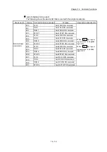
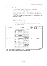
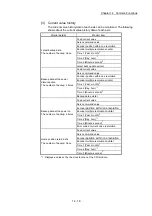
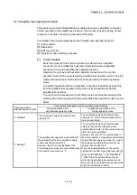
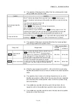
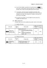
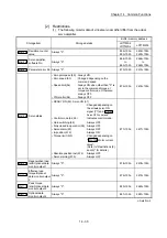
[2] Restrictions
(1) Some monitor data differ from the actual servo amplifier during amplifier-
less operation mode.
Storage item
Storage details
Buffer memory address
LD77MS2
LD77MS4
LD77MS16
Md.102
Deviation counter value Always "0".
852+100n
853+100n
2452+100n
2453+100n
Md.106
Servo amplifier
software No.
Always "0".
864+100n
to
869+100n
2464+100n
to
2469+100n
Md.107
Parameter error No.
Always "0".
870+100n
2470+100n
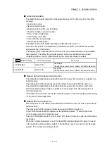
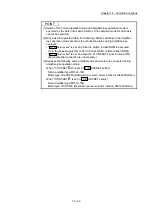
Md.108
Servo status
• Zero point pass (b0) : Always ON
• Zero speed (b3)
: Changed depending on the
command speed
• Speed limit (b4)
: Always ON when other than "0"
is set to the command torque at
torque control mode. Otherwise,
always OFF.
• PID control (b8)
: Always OFF
876+100n 2476+100n
• READY ON(b0), Servo ON(b1):
Changed depending on the all axis servo ON
signal[Y1] and "
Cd.100
Servo OFF command
".
• Control mode (b2, b3)
: Indicates control mode.
• Gain switching (b4)
: Always OFF
• Fully closed loop control (b5): Always OFF
• Servo alarm(b7)
: Always OFF
• In-position(b12)
: Always ON
• Torque limit(b13)
: Changed depending on
"
Md.104
Motor current
value
".
(Refer to "Restrictions
(2) and (3)" for details.)
• Absolute position lost(b14) : Always OFF
• Servo warning(b15)
: Always OFF
877+100n 2477+100n
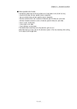
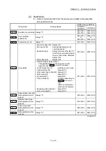
Md.109
Regenerative load ratio/
Optional data monitor
output 1
Always "0".
878+100n
2478+100n
Md.110
Effective load torque/
Optional data monitor
output 2
Always "0".
879+100n
2479+100n
Md.111
Peak torque ratio/
Optional data monitor
output 3
Always "0".
880+100n
2480+100n
Md.112
Optional data monitor
output 4
Always "0".
881+100n
2481+100n
n: Axis No.-1
Summary of Contents for MELSEC-L Series
Page 2: ......
Page 30: ...MEMO ...
Page 70: ...2 10 Chapter 2 System Configuration MEMO ...
Page 83: ...3 13 Chapter 3 Specifications and Functions MEMO ...
Page 103: ...3 33 Chapter 3 Specifications and Functions MEMO ...
Page 107: ...3 37 Chapter 3 Specifications and Functions MEMO ...
Page 111: ...3 41 Chapter 3 Specifications and Functions MEMO ...
Page 115: ...3 45 Chapter 3 Specifications and Functions MEMO ...
Page 140: ...4 22 Chapter 4 Installation Wiring and Maintenance of the Product MEMO ...
Page 253: ...5 113 Chapter 5 Data Used for Positioning Control MEMO ...
Page 342: ...5 202 Chapter 5 Data Used for Positioning Control MEMO ...
Page 438: ...7 20 Chapter 7 Memory Configuration and Data Process MEMO ...
Page 440: ...MEMO ...
Page 485: ...9 25 Chapter 9 Major Positioning Control MEMO ...
Page 594: ...9 134 Chapter 9 Major Positioning Control MEMO ...
Page 624: ...10 30 Chapter 10 High Level Positioning Control MEMO ...
Page 656: ...11 32 Chapter 11 Manual Control MEMO ...
Page 690: ...12 34 Chapter 12 Expansion Control MEMO ...
Page 798: ...13 108 Chapter 13 Control Sub Functions MEMO ...
Page 866: ...14 68 Chapter 14 Common Functions MEMO ...
Page 884: ...15 18 Chapter 15 Dedicated Instructions MEMO ...
Page 899: ...16 15 Chapter 16 Troubleshooting MEMO ...
Page 1036: ...Appendix 88 Appendices MEMO ...
Page 1039: ......


