


13 - 29
Chapter 13 Control Sub Functions
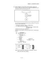
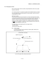
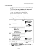
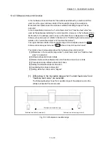
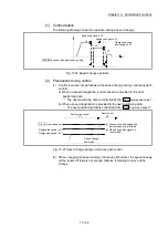
The following drawing shows the differences in the operation when "
Md.20
Current feed value
" and "
Md.21
Machine feed value
" are used in the moveable range
limit check.
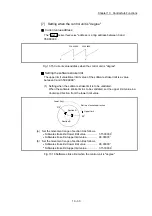
[Conditions]
Assume the current stop position is 2000, and the upper stroke limit is set to 5000.
5000
5000
Upper stroke limit
2000
2000
Stop position
Moveable range
Md. 20 Current feed value
Md. 21 Machine feed value
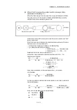
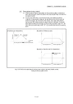
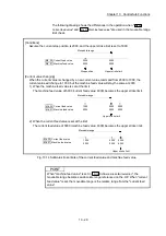
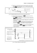
[Current value changing]
When the current value is changed by a new current value command from 2000 to 1000, the
current value will change to 1000, but the machine feed value will stay the same at 2000.
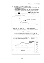
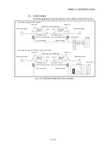
1) When the machine feed value is set at the limit
The machine feed value of 5000 (current feed value: 4000) becomes the upper stroke limit.
4000
5000
5000
6000
Upper stroke limit
1000
2000
Moveable range
Md. 20 Current feed value
Md. 21 Machine feed value
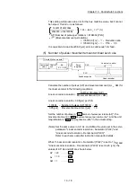
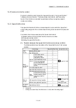
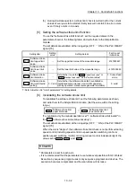
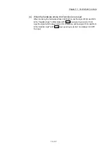
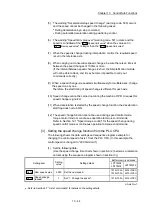
2) When the current feed value is set at the limit
The current feed value of 5000 (machine feed value: 6000) becomes the upper stroke limit.
4000
5000
5000
6000
Upper stroke limit
1000
2000
Moveable range
Md. 20 Current feed value
Md. 21 Machine feed value
Fig. 13.14 Software stroke limits of the current feed value and machine feed value
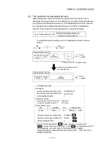
POINT
When "machine feed value" is set in "
Pr.14
Software stroke limit selection
", the
moveable range becomes an absolute range referenced on the OP. When "current
feed value" is set, the moveable range is the relative range from the "current feed
value".
Summary of Contents for MELSEC-L Series
Page 2: ......
Page 30: ...MEMO ...
Page 70: ...2 10 Chapter 2 System Configuration MEMO ...
Page 83: ...3 13 Chapter 3 Specifications and Functions MEMO ...
Page 103: ...3 33 Chapter 3 Specifications and Functions MEMO ...
Page 107: ...3 37 Chapter 3 Specifications and Functions MEMO ...
Page 111: ...3 41 Chapter 3 Specifications and Functions MEMO ...
Page 115: ...3 45 Chapter 3 Specifications and Functions MEMO ...
Page 140: ...4 22 Chapter 4 Installation Wiring and Maintenance of the Product MEMO ...
Page 253: ...5 113 Chapter 5 Data Used for Positioning Control MEMO ...
Page 342: ...5 202 Chapter 5 Data Used for Positioning Control MEMO ...
Page 438: ...7 20 Chapter 7 Memory Configuration and Data Process MEMO ...
Page 440: ...MEMO ...
Page 485: ...9 25 Chapter 9 Major Positioning Control MEMO ...
Page 594: ...9 134 Chapter 9 Major Positioning Control MEMO ...
Page 624: ...10 30 Chapter 10 High Level Positioning Control MEMO ...
Page 656: ...11 32 Chapter 11 Manual Control MEMO ...
Page 690: ...12 34 Chapter 12 Expansion Control MEMO ...
Page 798: ...13 108 Chapter 13 Control Sub Functions MEMO ...
Page 866: ...14 68 Chapter 14 Common Functions MEMO ...
Page 884: ...15 18 Chapter 15 Dedicated Instructions MEMO ...
Page 899: ...16 15 Chapter 16 Troubleshooting MEMO ...
Page 1036: ...Appendix 88 Appendices MEMO ...
Page 1039: ......


