

5 - 123
Chapter 5 Data Used for Positioning Control
Default value
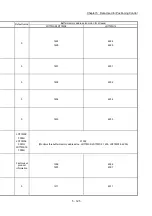
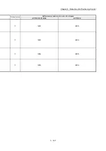
Buffer memory address (common for all axes)
LD77MS2/LD77MS4 LD77MS16
0
4272
4160
4161
4273
4164
4165
4274
4168
4169
4275
4172
4173
4276
4176
4177
4277
4180
4181
4278
4184
4185
4279
4188
4189
4280
4192
4193
4281
4196
4197
4282
4200
4201
4283
4204
4205
4284
4208
4209
4285
4212
4213
4286
4216
4217
4287
4220
4221
4158
4159
4162
4163
4166
4167
4170
4171
4174
4175
4178
4179
4182
4183
4186
4187
4190
4191
4194
4195
4198
4199
4202
4203
4206
4207
4210
4211
4214
4215
4218
4219
Pointer No.
Md.16
Md.17
Md.56
Axis warning occurrence
(Year: month)
Axis warning occurrence
(Day: hour)
Axis warning occurrence
(Minute: second)
Axis warning No.
Md.15
Md.14
Axis in which the
warning occurred
Ite
m
0
2
3
4
5
6
7
8
9
10
11
12
13
14
15
31316
1
31317 31318 31319 31320 31321 31322 31323 31324 31325 31326 31327 31328 31329 31330 31331
Servo warning
Md.58
1358
1359
1362
1363
1366
1367
1370
1371
1378
1379
1374
1375
1383
1382 1386
1387
1390
1391
1394
1395
1398
1399
1402
1403
1406
1407
1410
1411
1414
1415
1418
1419
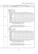
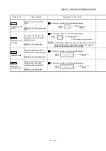
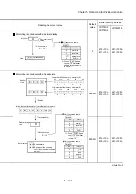
Indicates a pointer No. that is next to the pointer No. assigned to the latest of the existing warning history records.
Pointer No.
1422
Md.18
Md.16
Md.17
Md.56
Axis warning occurrence
(Year: month)
Axis warning occurrence
(Day: hour)
Axis warning occurrence
(Minute: second)
Axis warning No.
Md.15
Md.14
Axis in which the
warning occurred
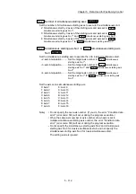
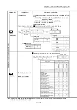
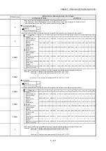
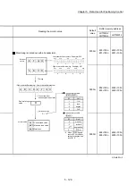
Warning history pointer
Item
LD77MS2/LD77MS4
Pointer No. 15 = Buffer memory addresses 1418 to 1421, 1487, 31331
Each history record is assigned a pointer No. in the range between 0 and 15.
If the pointer No. 15 has been assigned to a new record, the next record will be assigned the pointer number 0.
(A new record replaces an older record when a pointer No. is reassigned.)
Each group of buffer memory addresses storing a complete warning history record is assigned a pointer No.
Example: Pointer No. 0 = Buffer memory addresses 1358 to 1361, 1472, 31316
Pointer No. 1 = Buffer memory addresses 1362 to 1365, 1473, 31317
Pointer No. 2 = Buffer memory addresses 1366 to 1369, 1474, 31318
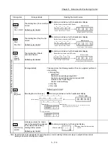
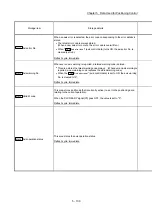
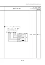
Indicates a pointer No. that is next to the pointer No. assigned to the latest of the existing warning history records.
4222
Md.18
Pointer No. 15 = Buffer memory addresses 4218 to 4221, 4287, 31331
Each history record is assigned a pointer No. in the range between 0 and 15.
If the pointer No. 15 has been assigned to a new record, the next record will be assigned the pointer number 0.
(A new record replaces an older record when a pointer No. is reassigned.)
Each group of buffer memory addresses storing a complete warning history record is assigned a pointer No.
Example: Pointer No. 0 = Buffer memory addresses 4158 to 4161, 4272, 31316
Pointer No. 1 = Buffer memory addresses 4162 to 4165, 4273, 31317
Pointer No. 2 = Buffer memory addresses 4166 to 4169, 4274, 31318
Warning history pointer
LD77MS16
0
2
3
4
5
6
7
8
9
10
11
12
13
14
15
31316
1
31317 31318 31319 31320 31321 31322 31323 31324 31325 31326 31327 31328 31329 31330 31331
1472
1360
1361
1473
1364
1365
1474
1368
1369
1372
1373
1475 1476
1376
1377
1477
1380
1381
1478
1384
1385
1479
1388
1389
1480
1392
1393
1481
1396
1397
1482
1400
1401
1483
1404
1405
1484
1408
1409
1485
1412
1413
1486
1416
1417
1487
1420
1421
Servo warning
Md.58
0
0000H
0000H
0000H
0000H
0
Summary of Contents for MELSEC-L Series
Page 2: ......
Page 30: ...MEMO ...
Page 70: ...2 10 Chapter 2 System Configuration MEMO ...
Page 83: ...3 13 Chapter 3 Specifications and Functions MEMO ...
Page 103: ...3 33 Chapter 3 Specifications and Functions MEMO ...
Page 107: ...3 37 Chapter 3 Specifications and Functions MEMO ...
Page 111: ...3 41 Chapter 3 Specifications and Functions MEMO ...
Page 115: ...3 45 Chapter 3 Specifications and Functions MEMO ...
Page 140: ...4 22 Chapter 4 Installation Wiring and Maintenance of the Product MEMO ...
Page 253: ...5 113 Chapter 5 Data Used for Positioning Control MEMO ...
Page 342: ...5 202 Chapter 5 Data Used for Positioning Control MEMO ...
Page 438: ...7 20 Chapter 7 Memory Configuration and Data Process MEMO ...
Page 440: ...MEMO ...
Page 485: ...9 25 Chapter 9 Major Positioning Control MEMO ...
Page 594: ...9 134 Chapter 9 Major Positioning Control MEMO ...
Page 624: ...10 30 Chapter 10 High Level Positioning Control MEMO ...
Page 656: ...11 32 Chapter 11 Manual Control MEMO ...
Page 690: ...12 34 Chapter 12 Expansion Control MEMO ...
Page 798: ...13 108 Chapter 13 Control Sub Functions MEMO ...
Page 866: ...14 68 Chapter 14 Common Functions MEMO ...
Page 884: ...15 18 Chapter 15 Dedicated Instructions MEMO ...
Page 899: ...16 15 Chapter 16 Troubleshooting MEMO ...
Page 1036: ...Appendix 88 Appendices MEMO ...
Page 1039: ......


