


7 - 15
Chapter 7 Memory Configuration and Data Process
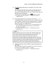
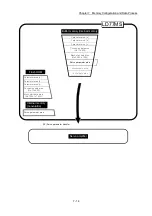
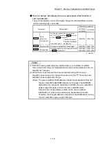
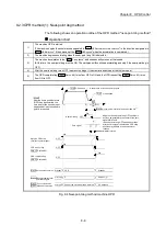
(10) Transmitting servo parameter from the buffer memory/internal
memory area to servo amplifier (
)
The servo parameter in the buffer memory/internal memory area is transmitted
to the servo amplifier by the following timing.
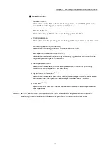
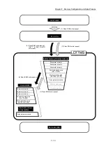
1) The servo parameter is transmitted to the servo amplifier when
communications with servo amplifier start.
The "expansion parameter" and "servo parameter" in the buffer memory
area is transmitted to the servo amplifier.
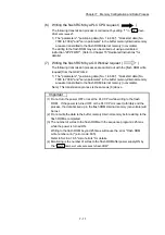
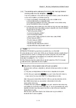
2) The following servo parameter in the buffer memory area are transmitted to
the internal memory (nonvolatile) and servo amplifier when the PLC READY
signal [Y0] turns from OFF to ON.
• "Auto tuning mode (PA08)"
• "Auto tuning response (PA09)"
• "Feed forward gain (PB04)"
• "Load to motor inertia ratio/load to motor mass ratio (PB06)"
• "Model loop gain (PB07)"
• "Position loop gain (PB08)"
• "Speed loop gain (PB09)"
• "Speed integral compensation (PB10)"
• "Speed differential compensation (PB11)"
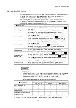
POINT
When the PLC READY signal [Y0] is turned ON, the error "SSCNET
communication error" (error code: 1205) occurs, "Rotation direction selection/travel
direction selection (PA14)" is changed by sequence program or the GX Works2
after the servo parameter is transmitted to servo amplifier (LED of the servo
amplifier is indicated "b_", "C_", or "d_").
When "Rotation direction selection/travel direction selection (PA14)" is changed,
transmit the servo parameter to servo amplifier.
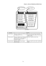
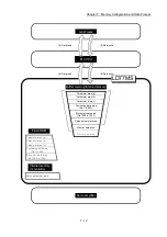
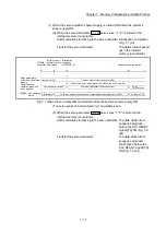
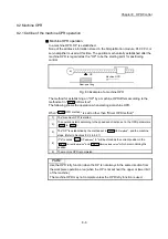
About the communication start with servo amplifier
Communication with servo amplifier is valid when following condition is realized
together.
1) The power of Simple Motion module and servo amplifier is turned ON.
2) When the servo parameter "
Pr.100
Servo series
" inside the buffer memory
area is set to the value other than "0" in Simple Motion module.
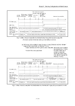
When the power is turned ON or the PLC CPU is reset, the data stored in the
flash ROM/internal memory (nonvolatile) is transmitted to the buffer
memory/internal memory.
Therefore the servo parameter "
Pr.100
Servo series
" inside the internal memory
(nonvolatile) is stored to the value other than "0", and communication with servo
amplifier is started when the power is turn ON in order of the servo amplifier,
Simple Motion module.
After the servo parameter stored in the internal memory (nonvolatile) is
transmitted to the servo amplifier.
Summary of Contents for MELSEC-L Series
Page 2: ......
Page 30: ...MEMO ...
Page 70: ...2 10 Chapter 2 System Configuration MEMO ...
Page 83: ...3 13 Chapter 3 Specifications and Functions MEMO ...
Page 103: ...3 33 Chapter 3 Specifications and Functions MEMO ...
Page 107: ...3 37 Chapter 3 Specifications and Functions MEMO ...
Page 111: ...3 41 Chapter 3 Specifications and Functions MEMO ...
Page 115: ...3 45 Chapter 3 Specifications and Functions MEMO ...
Page 140: ...4 22 Chapter 4 Installation Wiring and Maintenance of the Product MEMO ...
Page 253: ...5 113 Chapter 5 Data Used for Positioning Control MEMO ...
Page 342: ...5 202 Chapter 5 Data Used for Positioning Control MEMO ...
Page 438: ...7 20 Chapter 7 Memory Configuration and Data Process MEMO ...
Page 440: ...MEMO ...
Page 485: ...9 25 Chapter 9 Major Positioning Control MEMO ...
Page 594: ...9 134 Chapter 9 Major Positioning Control MEMO ...
Page 624: ...10 30 Chapter 10 High Level Positioning Control MEMO ...
Page 656: ...11 32 Chapter 11 Manual Control MEMO ...
Page 690: ...12 34 Chapter 12 Expansion Control MEMO ...
Page 798: ...13 108 Chapter 13 Control Sub Functions MEMO ...
Page 866: ...14 68 Chapter 14 Common Functions MEMO ...
Page 884: ...15 18 Chapter 15 Dedicated Instructions MEMO ...
Page 899: ...16 15 Chapter 16 Troubleshooting MEMO ...
Page 1036: ...Appendix 88 Appendices MEMO ...
Page 1039: ......


