


13 - 34
Chapter 13 Control Sub Functions
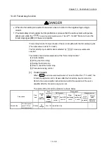
13.4.4 Hardware stroke limit function
DANGER
When the hardware stroke limit is required to be wired, ensure to wire it in the negative logic
using b-contact. If it is set in positive logic using a-contact, a serious accident may occur.
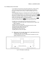
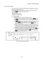
In the "hardware stroke limit function", limit switches are set at the upper/lower limit of
the physical moveable range, and the control is stopped (by deceleration stop) by the
input of a signal from the limit switch. Damage to the machine can be prevented by
stopping the control before the upper/lower limit of the physical moveable range is
reached.
The hardware stroke limit is able to use the following signals. (Refer to the "
Pr.80
External input signal selection
".)
External input signal of the servo amplifier
External input signal via CPU (buffer memory of LD77MS)
The details shown below explain about the "hardware stroke limit function".
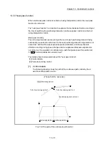
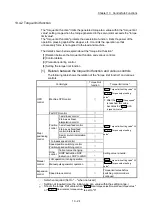
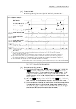
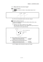
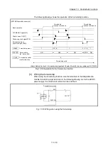
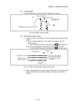
[1] Control details
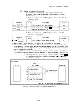
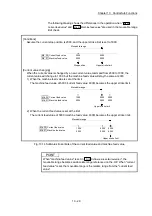
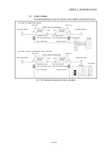
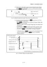
[2] Wiring the hardware stroke limit
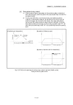
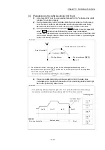
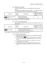
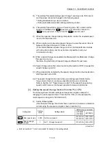
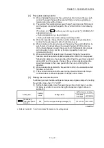
[3] Precautions during control
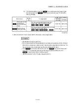
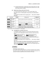
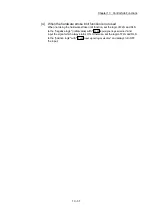
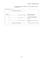
[4] When the hardware stroke limit function is not used
Summary of Contents for MELSEC-L Series
Page 2: ......
Page 30: ...MEMO ...
Page 70: ...2 10 Chapter 2 System Configuration MEMO ...
Page 83: ...3 13 Chapter 3 Specifications and Functions MEMO ...
Page 103: ...3 33 Chapter 3 Specifications and Functions MEMO ...
Page 107: ...3 37 Chapter 3 Specifications and Functions MEMO ...
Page 111: ...3 41 Chapter 3 Specifications and Functions MEMO ...
Page 115: ...3 45 Chapter 3 Specifications and Functions MEMO ...
Page 140: ...4 22 Chapter 4 Installation Wiring and Maintenance of the Product MEMO ...
Page 253: ...5 113 Chapter 5 Data Used for Positioning Control MEMO ...
Page 342: ...5 202 Chapter 5 Data Used for Positioning Control MEMO ...
Page 438: ...7 20 Chapter 7 Memory Configuration and Data Process MEMO ...
Page 440: ...MEMO ...
Page 485: ...9 25 Chapter 9 Major Positioning Control MEMO ...
Page 594: ...9 134 Chapter 9 Major Positioning Control MEMO ...
Page 624: ...10 30 Chapter 10 High Level Positioning Control MEMO ...
Page 656: ...11 32 Chapter 11 Manual Control MEMO ...
Page 690: ...12 34 Chapter 12 Expansion Control MEMO ...
Page 798: ...13 108 Chapter 13 Control Sub Functions MEMO ...
Page 866: ...14 68 Chapter 14 Common Functions MEMO ...
Page 884: ...15 18 Chapter 15 Dedicated Instructions MEMO ...
Page 899: ...16 15 Chapter 16 Troubleshooting MEMO ...
Page 1036: ...Appendix 88 Appendices MEMO ...
Page 1039: ......


