

10 - 27
Chapter 10 High-Level Positioning Control
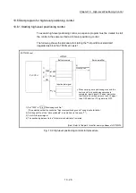
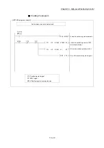
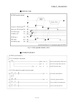
10.6.2 Example of a start program for high-level positioning control
The following shows an example of a start program for high-level positioning control in
which the 1st point "block start data" of axis 1 is started. (The block No. is regarded as
"7000".)
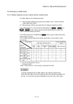
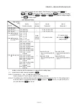
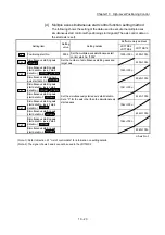
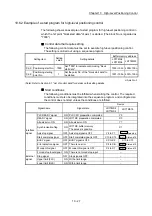
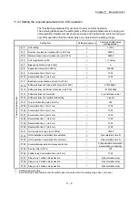
Control data that require setting
The following control data must be set to execute high-level positioning control.
The setting is carried out using a sequence program.
Setting item
Setting
value
Setting details
Buffer memory address
LD77MS2
LD77MS4
LD77MS16
Cd.3 Positioning start No. 7000
Set "7000" to indicate control using "block
start data".
1500+100n 4300+100n
Cd.4
Positioning starting
point No.
1
Set the point No. of the "block start data" to
be started.
1501+100n 4301+100n
n: Axis No.-1
(Note): Refer to Section 5.7 "List of control data" for details on the setting details.
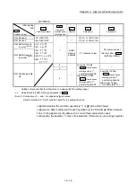
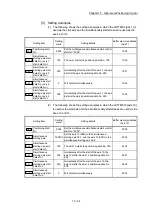
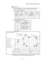
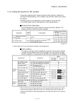
Start conditions
The following conditions must be fulfilled when starting the control. The required
conditions must also be integrated into the sequence program, and configured so
the control does not start unless the conditions are fulfilled.
Signal name
Signal state
Device
LD77MS2
LD77MS4
LD77MS16
Interface
signal
PLC READY signal
ON PLC CPU preparation completed
Y0
READY signal
ON LD77MS preparation completed
X0
All axis servo ON
ON All axis servo ON
Y1
Synchronization flag
ON
LD77MS buffer memory
The access is possible.
X1
Axis stop signal
OFF Axis stop signal is OFF
Y4 to Y7
Cd.180
Axis stop
Start complete signal
OFF Start complete signal is OFF
X10 to X13
Md.31
Status: b14
BUSY signal
OFF BUSY signal is OFF
XC to XF
X10 to X1F
Error detection signal
OFF There is no error
X8 to XB
Md.31
Status: b13
M code ON signal
OFF M code ON signal is OFF
X4 to X7
Md.31
Status: b12
External
signal
Forced stop input signal ON There is no forced stop input
–
Stop signal
OFF Stop signal is OFF
–
Upper limit (FLS)
ON Within limit range
–
Lower limit (RLS)
ON Within limit range
–
Summary of Contents for MELSEC-L Series
Page 2: ......
Page 30: ...MEMO ...
Page 70: ...2 10 Chapter 2 System Configuration MEMO ...
Page 83: ...3 13 Chapter 3 Specifications and Functions MEMO ...
Page 103: ...3 33 Chapter 3 Specifications and Functions MEMO ...
Page 107: ...3 37 Chapter 3 Specifications and Functions MEMO ...
Page 111: ...3 41 Chapter 3 Specifications and Functions MEMO ...
Page 115: ...3 45 Chapter 3 Specifications and Functions MEMO ...
Page 140: ...4 22 Chapter 4 Installation Wiring and Maintenance of the Product MEMO ...
Page 253: ...5 113 Chapter 5 Data Used for Positioning Control MEMO ...
Page 342: ...5 202 Chapter 5 Data Used for Positioning Control MEMO ...
Page 438: ...7 20 Chapter 7 Memory Configuration and Data Process MEMO ...
Page 440: ...MEMO ...
Page 485: ...9 25 Chapter 9 Major Positioning Control MEMO ...
Page 594: ...9 134 Chapter 9 Major Positioning Control MEMO ...
Page 624: ...10 30 Chapter 10 High Level Positioning Control MEMO ...
Page 656: ...11 32 Chapter 11 Manual Control MEMO ...
Page 690: ...12 34 Chapter 12 Expansion Control MEMO ...
Page 798: ...13 108 Chapter 13 Control Sub Functions MEMO ...
Page 866: ...14 68 Chapter 14 Common Functions MEMO ...
Page 884: ...15 18 Chapter 15 Dedicated Instructions MEMO ...
Page 899: ...16 15 Chapter 16 Troubleshooting MEMO ...
Page 1036: ...Appendix 88 Appendices MEMO ...
Page 1039: ......


